
Instruction Manual
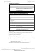
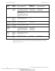
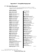
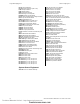
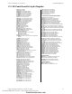

Table Of Contents
- Table of Contents
- Section 1 About This Manual
- Section 2 System Overview
- Section 3 Installation
- 3.1 Preparing for Installation
- 3.2 Installation Checklist
- 3.3 Mounting a Cabinet
- 3.4 Laying Out Equipment in Cabinet and Chassis
- 3.5 Installing the Control Panel
- 3.5.1 Control Panel Circuit Board & Keypad/Display Unit
- 3.5.2 Using NCA as Primary Display
- 3.5.3 Loop Expander Module
- 3.5.4 Network Control Module
- 3.5.5 Panel Circuit Modules and Other Option Boards
- 3.5.6 Overview
- 3.5.7 Connecting the Control Panel to AC Power
- 3.5.8 Checking AC Power
- 3.5.9 Installing and Connecting the Batteries
- 3.5.10 APS-6R Auxiliary Power Supply Connections
- 3.5.11 External DC Power Output Connections
- 3.5.12 NAC Connections & Releasing Circuits
- 3.5.13 Output Relay Connections
- 3.5.14 Backup-Alarm Switches
- 3.5.15 Installing a Transmitter Module TM-4
- 3.6 UL Power-limited Wiring Requirements
- 3.7 Installing Panel Circuit Modules
- 3.8 Auxiliary Relay Module (ARM-4): Product-Specific Details
- 3.9 Installing Remote Printers and/or CRT
- 3.10 Wiring a Signaling Line Circuit (SLC)
- Section 4 Applications
- Section 5 Testing the System
- Appendix A Power Supply Calculations
- Appendix B Electrical Specifications
- Appendix C Compatible Equipment
- Appendix D Canadian Applications
- Index

Electrical Specifications Wire Requirements
76 NFS-640 Installation Manual P/N 51332:B2 07/27/2004
Note: Lightning arresters required on circuits extending between buildings; 999 meter length
maximum to meet UL 1459.
Circuit
Type
Circuit
Function Wire Requirements
Distance
(feet/meters) Typical Wire Type
SLC
(power limited)
Connects to
intelligent and
addressable
modules.
Twisted-unshielded pair, 12 to 18 AWG
(3.1 to 0.78 mm
2
). 50 ohms maximum
per length of Style 6 & 7 loops. 50 ohms
per branch maximum for Style 4 loop.
12,500 ft. (3,810 m)
9,500 ft. (2,895.6 m)
6,000 ft. (1,828.8 m)
3,700 ft. (1,127.76 m)
12 AWG (3.1 mm
2
)
14 AWG (2.00 mm
2
)
16 AWG (1.30 mm
2
)
18 AWG (0.78 mm
2
)
or Untwisted, unshielded wire, in conduit
or outside of conduit.
Note: Maximum total capacitance of all SLC
wiring (both between conductors and from any
conductor to ground) should not exceed 0.5
mircofarads.
1,000 ft. (304.8 m) 12 to 18 AWG (3.1 to 0.78 mm
2
)
EIA-485
(power limited)
Connects to
LCD-80, ACS
modules, or
TM-4
Transmitter
Twisted-shielded pair with a
characteristic impedance of 120 ohms.
18 AWG (0.78 mm
2
) minimum.
6,000/1829
(max)
16 AWG (1.30 mm
2
)
EIA-232
(power limited)
Connects to
Printers, CRT,
or PC.
Twisted-shielded pair.
18 AWG (0.78 mm
2
) minimum.
50/15.24
(without modem)
16 AWG (1.30 mm
2
)
IDC
Initiating
Device Circuit
FMM-1, FMM-
101, XP5-M
(power limited)
12-18 AWG (3.1 to 0.78 mm
2
).
Maximum circuit resistance is 20 ohms.
12 to 18 AWG (3.1 to 0.78 mm
2
)
NAC
Notification
Appliance
Circuit
XP5-C, FCM-1
(power limited)
12-18 AWG (3.1 to 0.78 mm
2
).
At alarm current level, no more than a
1.2 V drop at the end of the circuit, or
sized to provide the minimum rated
operating voltage of the appliances
used.
To meet 1.2 V drop, or
sized to provide the
minimum rated
operating voltage of
the appliances used.
12 to 18 AWG (3.1 to 0.78 mm
2
)
24 VDC Power
Runs
(power-
limited)
To TM-4
Transmitter,
Annunciator
and FCM-1
modules
12-18 AWG (3.1 to 0.78 mm
2
).
Size wire so that no more than 1.2 V
drop across wire run from supply source
to end of any branch.
To meet 1.2 volt drop 12 to 18 AWG (3.1 to 0.78 mm
2
)
CHG-120 External
battery
charger
12 AWG (3.1 mm
2
) in conduit 20/6.1 (max) 12 AWG (3.1 mm
2
)
Table 16 Wire Requirements
Technical Manuals Online! - http://www.tech-man.com
firealarmresources.com