
Instruction Manual
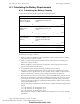
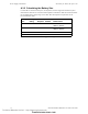
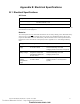
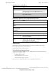
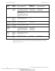
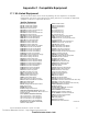
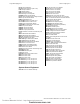

Table Of Contents
- Table of Contents
- Section 1 About This Manual
- Section 2 System Overview
- Section 3 Installation
- 3.1 Preparing for Installation
- 3.2 Installation Checklist
- 3.3 Mounting a Cabinet
- 3.4 Laying Out Equipment in Cabinet and Chassis
- 3.5 Installing the Control Panel
- 3.5.1 Control Panel Circuit Board & Keypad/Display Unit
- 3.5.2 Using NCA as Primary Display
- 3.5.3 Loop Expander Module
- 3.5.4 Network Control Module
- 3.5.5 Panel Circuit Modules and Other Option Boards
- 3.5.6 Overview
- 3.5.7 Connecting the Control Panel to AC Power
- 3.5.8 Checking AC Power
- 3.5.9 Installing and Connecting the Batteries
- 3.5.10 APS-6R Auxiliary Power Supply Connections
- 3.5.11 External DC Power Output Connections
- 3.5.12 NAC Connections & Releasing Circuits
- 3.5.13 Output Relay Connections
- 3.5.14 Backup-Alarm Switches
- 3.5.15 Installing a Transmitter Module TM-4
- 3.6 UL Power-limited Wiring Requirements
- 3.7 Installing Panel Circuit Modules
- 3.8 Auxiliary Relay Module (ARM-4): Product-Specific Details
- 3.9 Installing Remote Printers and/or CRT
- 3.10 Wiring a Signaling Line Circuit (SLC)
- Section 4 Applications
- Section 5 Testing the System
- Appendix A Power Supply Calculations
- Appendix B Electrical Specifications
- Appendix C Compatible Equipment
- Appendix D Canadian Applications
- Index

NFS-640 Installation Manual P/N 51332:B2 07/27/2004 73
Appendix B Electrical Specifications
B.1 Electrical Specifications
AC Power
Note: If using an auxiliary power supply such as APS-6R, ACPS-2406, or audio amplifiers, refer to the
documentation for that equipment.
Batteries
The control panel uses only
sealed lead-acid batteries for secondary standby power. Maximum battery
capacity for the control panel’s integral main power supply is 55 AH. Batteries larger than 25 AH
require the NFS-LBB or other UL-listed battery cabinet. The table below contains specifications for
batteries that can be used with the control panel; see also Appendix A.3.2 “Calculating the Battery
Size”:
Component Values
Main Power Supply 120 VAC, 50/60 Hz, 3.0 A; or
240 VAC, 50/60 Hz, 1.5 A
Wire size Maximum 12 AWG (3.1 mm
2
) with 600 VAC insulation
Charger Description Specifications
Main Power
Supply
An internal battery charger
for 12 AH to 55 AH
Dual Rate: High Charge: 29.1 VDC
Normal Float Charge: 27.6 VDC
Charging Current: 2.0 A max (1.5 A typical)
CHG-120
Battery Charger
An external battery charger
designed to charge lead-
acid batteries between 25
AH and 120 AH
Dual Rate: High Charge: 28.1 VDC
Normal Float Charge: 27.6 VDC
Charging Current: 4.5 A
ACPS-2406
Auxiliary
Charger/Power
Supply
An internal battery charger
for 7AH to 25 AH
Normal Float Charge: 27.6 VDC
Charging Current: 1.1 A max (0.750 A
typical)
Technical Manuals Online! - http://www.tech-man.com
firealarmresources.com