
Instruction Manual
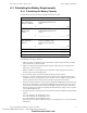
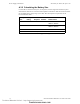
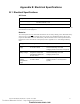
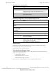
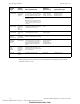
Table Of Contents
- Table of Contents
- Section 1 About This Manual
- Section 2 System Overview
- Section 3 Installation
- 3.1 Preparing for Installation
- 3.2 Installation Checklist
- 3.3 Mounting a Cabinet
- 3.4 Laying Out Equipment in Cabinet and Chassis
- 3.5 Installing the Control Panel
- 3.5.1 Control Panel Circuit Board & Keypad/Display Unit
- 3.5.2 Using NCA as Primary Display
- 3.5.3 Loop Expander Module
- 3.5.4 Network Control Module
- 3.5.5 Panel Circuit Modules and Other Option Boards
- 3.5.6 Overview
- 3.5.7 Connecting the Control Panel to AC Power
- 3.5.8 Checking AC Power
- 3.5.9 Installing and Connecting the Batteries
- 3.5.10 APS-6R Auxiliary Power Supply Connections
- 3.5.11 External DC Power Output Connections
- 3.5.12 NAC Connections & Releasing Circuits
- 3.5.13 Output Relay Connections
- 3.5.14 Backup-Alarm Switches
- 3.5.15 Installing a Transmitter Module TM-4
- 3.6 UL Power-limited Wiring Requirements
- 3.7 Installing Panel Circuit Modules
- 3.8 Auxiliary Relay Module (ARM-4): Product-Specific Details
- 3.9 Installing Remote Printers and/or CRT
- 3.10 Wiring a Signaling Line Circuit (SLC)
- Section 4 Applications
- Section 5 Testing the System
- Appendix A Power Supply Calculations
- Appendix B Electrical Specifications
- Appendix C Compatible Equipment
- Appendix D Canadian Applications
- Index

Calculating the Battery Requirements Power Supply Calculations
NFS-640 Installation Manual P/N 51332:B2 07/27/2004 71
A.3 Calculating the Battery Requirements
A.3.1 Calculating the Battery Capacity
Use this table to determine the battery capacity needed for the system:
The following notes apply to Table 14:
1. NFPA 72-1999 Local, Proprietary, and Central Station systems requires 24 hours of standby
power followed by 5 minutes in alarm.
2. NFPA 72-1999 Auxiliary and Remote Station Systems require 60 hours or standby power
followed by 5 minutes in alarm.
3. Batteries installed in a system powered by an automatic starting engine generator need to
provide at least 4 hours of standby power.
4. Factory Mutual requires 90 hours of standby for deluge-preaction systems.
5. Emergency voice/alarm communications systems require 2 hours of operation in the alarm
condition. Due to the sporadic nature of voice operation, however, NFPA 72-1999 permits 15
minutes of operation at a maximum connected load to equal 2 hours of normal use.
6. If the total exceeds 25 AH, the system requires a separate NFS-LBB battery enclosure for two
PS-12550, 55 AH batteries in a separate NFS-LBB enclosure. If the total exceeds 55 AH, the
system requires an auxiliary battery charger with sufficient amp-hour capacity; this charger
must be UL-listed for Fire-Protective Signaling. If CHG-120 battery charger is used, it requires
a second NFS-LBB enclosure.
7. The following battery derating factors must be used for Canadian installations using NFS-640
charger:
• For a 12 AH battery, use derating factor of 1.2
• For a 25 AH battery, use derating factor of 1.5
• For a 55 AH battery, use derating factor of 1.8
When batteries are charged by CHG-120 charger use a derating factor of 1.2 for 25 AH and 55
AH batteries.
Current (amps) X Time (hours) = AH
Secondary Non-Fire
Alarm Current (from
column 3 in Table 12)
________________ X
Required Secondary Non-Fire
Alarm Standby Time (24 or 60
hours)
________________ = _________AH
APS-6R
Standby Load
Current
________________
X
Required Secondary Non-Fire
Alarm Standby Time (24 or 60
hours)
________________ = _________AH
Secondary Fire
Alarm Load (from
Table 13)
________________
X
Required Fire Alarm Standby
Time: (for 5 minutes, enter
0.084; for 15 minutes, enter
0.25)
________________
= _________AH
Sum Column for Total Secondary Amp Hours calculated = _________AH
Multiply by the derating factor x 1.2 (see Note 7) = _________AH
Battery Size – Total Secondary Amp Hours Required = _________AH
Table 14 Secondary Power Standby and Fire Alarm Load
Technical Manuals Online! - http://www.tech-man.com
firealarmresources.com