
Instruction Manual
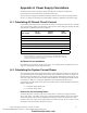
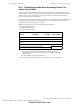
Table Of Contents
- Table of Contents
- Section 1 About This Manual
- Section 2 System Overview
- Section 3 Installation
- 3.1 Preparing for Installation
- 3.2 Installation Checklist
- 3.3 Mounting a Cabinet
- 3.4 Laying Out Equipment in Cabinet and Chassis
- 3.5 Installing the Control Panel
- 3.5.1 Control Panel Circuit Board & Keypad/Display Unit
- 3.5.2 Using NCA as Primary Display
- 3.5.3 Loop Expander Module
- 3.5.4 Network Control Module
- 3.5.5 Panel Circuit Modules and Other Option Boards
- 3.5.6 Overview
- 3.5.7 Connecting the Control Panel to AC Power
- 3.5.8 Checking AC Power
- 3.5.9 Installing and Connecting the Batteries
- 3.5.10 APS-6R Auxiliary Power Supply Connections
- 3.5.11 External DC Power Output Connections
- 3.5.12 NAC Connections & Releasing Circuits
- 3.5.13 Output Relay Connections
- 3.5.14 Backup-Alarm Switches
- 3.5.15 Installing a Transmitter Module TM-4
- 3.6 UL Power-limited Wiring Requirements
- 3.7 Installing Panel Circuit Modules
- 3.8 Auxiliary Relay Module (ARM-4): Product-Specific Details
- 3.9 Installing Remote Printers and/or CRT
- 3.10 Wiring a Signaling Line Circuit (SLC)
- Section 4 Applications
- Section 5 Testing the System
- Appendix A Power Supply Calculations
- Appendix B Electrical Specifications
- Appendix C Compatible Equipment
- Appendix D Canadian Applications
- Index

Power Supply Calculations Calculating the System Current Draws
70 NFS-640 Installation Manual P/N 51332:B2 07/27/2004
A.2.1 Calculating the Maximum Secondary Power Fire
Alarm Current Draw
Use the table below to determine the maximum current requirements of secondary power source
during fire alarm conditions. The result obtained is the amount of current that the batteries must be
able to supply to the fire alarm system. Use the result in Table 14 to determine the size of the
batteries needed for the fire alarm system.
Results taken from the table below assume that, while in a fire alarm condition, batteries must feed
the main power supply (and any additional supplies such as the APS-6R and AA-30) with the
maximum rated power each supply can provide.
Note: The Secondary Fire Alarm Load cannot exceed the following:
• 9 A with PS-12120 batteries.
• 12 A with PS-12250 batteries.
• 20 A with PS-12550 batteries.
Contact rating (maximum current) for battery-switching relay in the control panel
Device Quantity
Current
(in amps)
Total
Current/Type
Alarm Current, from Table 12, col 2 =
APS-6R
1
1. Actual load current may be used in place of maximum rated supply current. To
calculate actual load current, sum the current draws for each appliance connected to
APS-6R supplies.
[] X 6 =
AA-30
2
2. Exclude Amplifiers that are employed for backup.
[] X 3 =
AA-120
2
[ ] X 7.3 =
Sum Column for Secondary Fire Alarm Load =
Table 13 Maximum Secondary Power Fire Alarm Current Draw
Technical Manuals Online! - http://www.tech-man.com
firealarmresources.com