
Instruction Manual
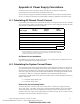
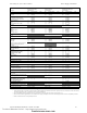
Table Of Contents
- Table of Contents
- Section 1 About This Manual
- Section 2 System Overview
- Section 3 Installation
- 3.1 Preparing for Installation
- 3.2 Installation Checklist
- 3.3 Mounting a Cabinet
- 3.4 Laying Out Equipment in Cabinet and Chassis
- 3.5 Installing the Control Panel
- 3.5.1 Control Panel Circuit Board & Keypad/Display Unit
- 3.5.2 Using NCA as Primary Display
- 3.5.3 Loop Expander Module
- 3.5.4 Network Control Module
- 3.5.5 Panel Circuit Modules and Other Option Boards
- 3.5.6 Overview
- 3.5.7 Connecting the Control Panel to AC Power
- 3.5.8 Checking AC Power
- 3.5.9 Installing and Connecting the Batteries
- 3.5.10 APS-6R Auxiliary Power Supply Connections
- 3.5.11 External DC Power Output Connections
- 3.5.12 NAC Connections & Releasing Circuits
- 3.5.13 Output Relay Connections
- 3.5.14 Backup-Alarm Switches
- 3.5.15 Installing a Transmitter Module TM-4
- 3.6 UL Power-limited Wiring Requirements
- 3.7 Installing Panel Circuit Modules
- 3.8 Auxiliary Relay Module (ARM-4): Product-Specific Details
- 3.9 Installing Remote Printers and/or CRT
- 3.10 Wiring a Signaling Line Circuit (SLC)
- Section 4 Applications
- Section 5 Testing the System
- Appendix A Power Supply Calculations
- Appendix B Electrical Specifications
- Appendix C Compatible Equipment
- Appendix D Canadian Applications
- Index

Calculating the System Current Draws Power Supply Calculations
NFS-640 Installation Manual P/N 51332:B2 07/27/2004 69
Category
Calculation Column 1
Primary, Non-Fire Alarm
Current (amps)
Calculation Column 2
Primary, Fire Alarm
Current (amps)
Calculation Column 3
Secondary, Non-Fire Alarm
Current (amps)
Qty X [current draw]= Total Qty X [current draw]= Total Qty X [current draw]= Total
CPU-640
KDM-2
LEM-320
1
[]
0 / 1
x [0.230] =
x [0.094]=
x [0.100]=
1
[]
0 / 1
x [0.230] =
x [0.094]=
x [0.100]=
1
[]
0 / 1
x [0.230] =
x [0.040]=
x [0.100]=
SLC loop
1
:
with jumper JP12 cut on CPU
or without jumper JP12 cut on CPU
0/1/2
x [0.200]=
x [0.400]=
0/1/2
x [0.200]=
x [0.400]=
0/1/2
x [0.200]=
x [0.400]=
NCA (back light on)
NCM-W, NCM-F
TM-4
DPI-232 (Refer to Doc. 51499)
[]
[]
[]
[]
x [0.400]=
x [0.110]=
x [0.110]=
x [ ]=
[]
[]
[]
[]
x [0.400]=
x [0.110]=
x [0.175]=
x [ ]=
[]
[]
[]
[]
x [0.400]=
x [0.110]=
x [0.110]=
x [ ]=
APS-6R
ACPS-2406
[]
[]
x [0.025]=
x [0.0013]=
ICM-4RK, ICM-4, CRM-4, CRM-4RK
ICE-4
CRE-4
DCM-4RK, DCM-4
VCE-4
VCM-4RK, VCM-4
[]
[]
[]
[]
[]
x [0.007]=
x [0.001]=
N/A
x [0.008]=
x [0.001]=
x [0.007]=
[]
[]
[]
[]
[]
x [0.072]=
x [0.065]=
x [0.065]=
x [0.080]=
x [0.040]=
x [0.040]=
[]
[]
[]
[]
[]
x [0.007]=
x [0.001]=
N/A
x [0.008]=
x [0.001]=
x [0.007]=
ARM-4 Auxiliary Relay
[ ] x [0.146]=
AA-30
AA-100, AA-120
[]
[]
x [0.045]=
x [0.050]=
ACM-24AT
ACM-48A
AEM-24AT
AEM-48A
[]
[]
[]
[]
x [0.016]=
x [0.016]=
x [0.002]=
x [0.002]=
[]
[]
[]
[]
x [0.070]=
x [0.070]=
x [0.056]=
x [0.056]=
[]
[]
[]
[]
x [0.016]=
x [0.016]=
x [0.002]=
x [0.002]=
Maximum number of LEDs illuminated on
these annunciators during non-fire
conditions:
[ ] x [0.0054]=
[ ] x [0.0054]=
AFM-16AT, AFM-32A
ACM-16AT, ACM-32A
AEM-16AT, AEM-32A
[]
[]
[]
x [0.040]=
x [0.040]=
x [0.002]=
[]
[]
[]
x [0.056]=
x [0.056]=
x [0.018]=
[]
[]
[]
x [0.040]=
x [0.040]=
x [0.002]=
AFM-16A
LCD-80, LCD-80TM
ACM-8R (refer to Doc. 15342)
LDM (refer to Doc. 15885)
UZC-256
[]
[]
[]
[]
[]
x [0.025]=
x [0.100]=
x [ ]=
x [ ]=
x [0.035]=
[]
[]
[]
[]
[]
x [0.065]=
x [0.100]=
x [ ]=
x [ ]=
x [0.085]=
[]
[]
[]
[]
[]
x [0.025]=
x [0.050]=
x [ ]=
x [ ]=
x [0.035]=
AMG-1, AMG-E
FFT-7, FFT-7S
RM-1
[]
[]
[]
x [0.060]=
x [0.060]=
x [0.020]=
[]
[]
[]
x [0.060]=
x [0.120]=
x [0.020]=
[]
[]
[]
x [0.060]=
x [0.060]=
x [0.020]=
FZM-1, MMX-2 [ ] x [0.0094]= [ ] x [0.090]= [ ] x [0.0094]=
XPIQ (Refer to Doc. 51013) []x []= []x []= []x []=
RPT-W, RPT-WF, RPT-F
RPT-485W, RPT-485WF
[ ] x [0.017]= [ ] x [0.017]= [ ] x [0.017]=
RFX (Refer to Doc. 51012) [ ] x [ ]= [ ] x [ ]= [ ] x [ ]=
UDACT Communicator
VEC-25/50
with optional FC-AAM25
[]
[]
[]
x [0.040]=
x [0.215]=
x [0.245]=
[]
[]
[]
x [0.100]=
x [1.215]=
x [2.215]=
[]
[]
[]
x [0.040]=
x [0.215]=
x [0.245]=
Four-Wire Smoke Detectors
2
[]
[]
x [ ]=
x [ ]=
[]
[]
x [ ]=
x [ ]=
[]
[]
x [ ]=
x [ ]=
Power Supervision Relay
(A77-716B)
[ ] x [0.020]= [ ] x [0.020]= [ ] x [0.020]=
Notification Appliance powered from Main
Power Supply
3
[]
[]
x [ ]=
x [ ]=
DHX-501, FSD-751RP, FSD-751RPL
(Duct Detectors with internal relays)
Refer to installation document
[]
[]
x [ ]=
x [ ]=
[]
[]
x [ ]=
x [ ]=
[]
[]
x [ ]=
x [ ]=
CHG-120 Battery Charger
[ ] x [0.060]=
Local Energy Municipal Box
[] x [ ]=
Compatable Devices not listed above
4
[]
[]
x [ ]=
x [ ]=
[]
[]
x [ ]=
x [ ]=
[]
[]
x [ ]=
x [ ]=
Sum each column for totals Primary, non-alarm: Primary, alarm: Secondary, non-alarm:
Table 12 System Draw Current Calculations
1. Value represents an SLC’s maximum current draw. Refer to device datasheets for individual current draws. If jumper JP12 is cut, total device current cannot exceed
200 mA; if jumper JP12 is not cut, total device current cannot exceed 400 mA.
2. The total regulated load current supplied to four-wire smoke detector and power supervision relays cannot exceed 1.25 A.
3. Enter the total notification appliance draw from the Main Power Supply, excluding the current from APS-6R supplies. Refer to Device Compatibility Document.
4. Refer to manual and/or Device Compatibility Document.
Technical Manuals Online! - http://www.tech-man.com
firealarmresources.com