
Instruction Manual
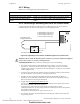
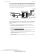
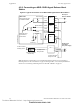
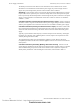
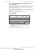
Table Of Contents
- Table of Contents
- Section 1 About This Manual
- Section 2 System Overview
- Section 3 Installation
- 3.1 Preparing for Installation
- 3.2 Installation Checklist
- 3.3 Mounting a Cabinet
- 3.4 Laying Out Equipment in Cabinet and Chassis
- 3.5 Installing the Control Panel
- 3.5.1 Control Panel Circuit Board & Keypad/Display Unit
- 3.5.2 Using NCA as Primary Display
- 3.5.3 Loop Expander Module
- 3.5.4 Network Control Module
- 3.5.5 Panel Circuit Modules and Other Option Boards
- 3.5.6 Overview
- 3.5.7 Connecting the Control Panel to AC Power
- 3.5.8 Checking AC Power
- 3.5.9 Installing and Connecting the Batteries
- 3.5.10 APS-6R Auxiliary Power Supply Connections
- 3.5.11 External DC Power Output Connections
- 3.5.12 NAC Connections & Releasing Circuits
- 3.5.13 Output Relay Connections
- 3.5.14 Backup-Alarm Switches
- 3.5.15 Installing a Transmitter Module TM-4
- 3.6 UL Power-limited Wiring Requirements
- 3.7 Installing Panel Circuit Modules
- 3.8 Auxiliary Relay Module (ARM-4): Product-Specific Details
- 3.9 Installing Remote Printers and/or CRT
- 3.10 Wiring a Signaling Line Circuit (SLC)
- Section 4 Applications
- Section 5 Testing the System
- Appendix A Power Supply Calculations
- Appendix B Electrical Specifications
- Appendix C Compatible Equipment
- Appendix D Canadian Applications
- Index

Applications Releasing Applications
64 NFS-640 Installation Manual P/N 51332:B2 07/27/2004
4.5.6 Connecting an NBG-12LRA Agent Release-Abort
Station
Figure 41 Typical Connections for an NBG-12LRA Agent Release-Abort Station
Note: If using the on-board NACs, see Circuit Requirements for Section 4.5.4 “Connecting a
Releasing Device to the Control Panel” on page 62. If using FCM-1, see Circuit Requirements for
Section 4.5.5 “Connecting a Releasing Device to the FCM-1 Module” on page 63.
+
+
–
–
–
–
+
+
+
1
2
4
6
5
7 -
6 +
1
2
3
4
0
–
–
+
+
–
–
+
–
–
+
SLC loop to
FACP or LEM-320
FCM-1
FRM-1
FMM-1
FMM-101
Black
Red
Yellow
Violet
Black
Red
Yellow
Violet
Non-resettable +24 VDC
from main power supply
Manual Abort
Manual Release
Normal
Release
NBG-12LRA
See Document 51369
for installation details.
ELR mode R-47K
supervised and
power-limited
RedBrown
24 VDC UL-listed
releasing device
C.
N.O.
REL-47K
(use with Type Code
Rel Ckt ULC)
NBG640-NBG12LRA.cdr
System
Common (–)
24 VDC power
from FACP’s
main power supply
N.C.
Power Supervision
Relay A77-716B
N.C. Supervision
Relay Contact
Technical Manuals Online! - http://www.tech-man.com
firealarmresources.com