
Instruction Manual
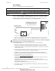
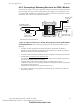
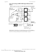
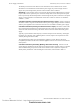
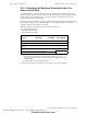
Table Of Contents
- Table of Contents
- Section 1 About This Manual
- Section 2 System Overview
- Section 3 Installation
- 3.1 Preparing for Installation
- 3.2 Installation Checklist
- 3.3 Mounting a Cabinet
- 3.4 Laying Out Equipment in Cabinet and Chassis
- 3.5 Installing the Control Panel
- 3.5.1 Control Panel Circuit Board & Keypad/Display Unit
- 3.5.2 Using NCA as Primary Display
- 3.5.3 Loop Expander Module
- 3.5.4 Network Control Module
- 3.5.5 Panel Circuit Modules and Other Option Boards
- 3.5.6 Overview
- 3.5.7 Connecting the Control Panel to AC Power
- 3.5.8 Checking AC Power
- 3.5.9 Installing and Connecting the Batteries
- 3.5.10 APS-6R Auxiliary Power Supply Connections
- 3.5.11 External DC Power Output Connections
- 3.5.12 NAC Connections & Releasing Circuits
- 3.5.13 Output Relay Connections
- 3.5.14 Backup-Alarm Switches
- 3.5.15 Installing a Transmitter Module TM-4
- 3.6 UL Power-limited Wiring Requirements
- 3.7 Installing Panel Circuit Modules
- 3.8 Auxiliary Relay Module (ARM-4): Product-Specific Details
- 3.9 Installing Remote Printers and/or CRT
- 3.10 Wiring a Signaling Line Circuit (SLC)
- Section 4 Applications
- Section 5 Testing the System
- Appendix A Power Supply Calculations
- Appendix B Electrical Specifications
- Appendix C Compatible Equipment
- Appendix D Canadian Applications
- Index

Applications Releasing Applications
62 NFS-640 Installation Manual P/N 51332:B2 07/27/2004
4.5.3 Wiring
References to wiring diagrams for releasing applications:
4.5.4 Connecting a Releasing Device to the Control Panel
Use TB3 (NAC#4), TB4 (NAC#3), TB5 (NAC#2), or TB6 (NAC#1) on the control panel for
NAC⁄Releasing Circuits. Only one releasing device can be installed per NAC.
Figure 39 Typical Style 4 Connection of a Releasing Device to Control Panel
Circuit Requirements. When connecting a releasing device, note the following:
1. The control panel provides four NAC/Releasing Circuits (Style Y or Z). Each circuit can
provide 2.5 A. Total current drawn from the power supply cannot exceed 6 A in an alarm
condition (refer to Table 12, “System Draw Current Calculations,” on page 69). Use UL-listed
24 VDC appliances only.
2. Circuits are supervised and power-limited (except if configured according to Note 4a below).
For more information, refer to the Device Compatibility Document.
3. For NFPA 13 and 15 applications, disable the Soak Timer (Soak=0000); for NFPA 16
applications, set the Soak Timer (0600-0900 seconds). Refer to the NFS-640 Programming
Manual for instructions on setting the Soak Timer.
4. In applications not requiring power-limited circuits
–
a) If the application does not require supervising the releasing device against shorts, End-of-
Line devices (P/N REL-2.2K) are not required;
b) Limited energy cable cannot be used for wiring of a releasing device circuit;
c) Maintain a 0.25 inch (6.35 mm) spacing between the releasing circuit device wiring and any
power-limited circuit wiring; and
d) Program the releasing circuit for Type Code
RELEASE CKT.
5. The releasing circuit must be programmed with a releasing type code listed in the NFS-640
Programming Manual.
To connect Refer to
A releasing device to the control panel. Section 4.5.4 “Connecting a Releasing Device to the Control Panel”.
A releasing device to the FCM-1 Module. Section 4.5.5 “Connecting a Releasing Device to the FCM-1 Module”.
An NBG-12LRA Agent Release-Abort
Station.
Section 4.5.6 “Connecting an NBG-12LRA Agent Release-Abort
Station”.
+
–
nfs640-relconn1.cdr
REL-2.2K
Compatible UL-listed
24 VDC releasing device
B+ NAC/Releasing output (source)
B– NAC/Releasing output (source)
A+ Class A (return for NAC only)
A– Class A (return for NAC only)
Note: See text below for circuit requirements.
!
WARNING: Do not enable the BACKUP option switch for any of the four Notification Appliance
Circuits (NACs) if they are used for releasing functions!
Technical Manuals Online! - http://www.tech-man.com
firealarmresources.com