
Instruction Manual
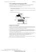
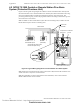
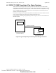
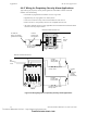
Table Of Contents
- Table of Contents
- Section 1 About This Manual
- Section 2 System Overview
- Section 3 Installation
- 3.1 Preparing for Installation
- 3.2 Installation Checklist
- 3.3 Mounting a Cabinet
- 3.4 Laying Out Equipment in Cabinet and Chassis
- 3.5 Installing the Control Panel
- 3.5.1 Control Panel Circuit Board & Keypad/Display Unit
- 3.5.2 Using NCA as Primary Display
- 3.5.3 Loop Expander Module
- 3.5.4 Network Control Module
- 3.5.5 Panel Circuit Modules and Other Option Boards
- 3.5.6 Overview
- 3.5.7 Connecting the Control Panel to AC Power
- 3.5.8 Checking AC Power
- 3.5.9 Installing and Connecting the Batteries
- 3.5.10 APS-6R Auxiliary Power Supply Connections
- 3.5.11 External DC Power Output Connections
- 3.5.12 NAC Connections & Releasing Circuits
- 3.5.13 Output Relay Connections
- 3.5.14 Backup-Alarm Switches
- 3.5.15 Installing a Transmitter Module TM-4
- 3.6 UL Power-limited Wiring Requirements
- 3.7 Installing Panel Circuit Modules
- 3.8 Auxiliary Relay Module (ARM-4): Product-Specific Details
- 3.9 Installing Remote Printers and/or CRT
- 3.10 Wiring a Signaling Line Circuit (SLC)
- Section 4 Applications
- Section 5 Testing the System
- Appendix A Power Supply Calculations
- Appendix B Electrical Specifications
- Appendix C Compatible Equipment
- Appendix D Canadian Applications
- Index

Applications Fire/Security Applications
60 NFS-640 Installation Manual P/N 51332:B2 07/27/2004
4.4.5 Wiring for Proprietary Security Alarm Applications
Typical wiring for proprietary security alarm applications with FMM-1 modules or XP5-M
modules. Note the following:
• The module is programmed with software SECURITY Type Code.
• Supplementary use only applies to UL-listed systems.
• NAC devices used for security cannot be shared with fire NAC devices.
• Refer to the Device Compatibility Document for compatible NAC devices.
• All monitor modules used for security application must be installed in the NFS-640 cabinet
with STS-1 Security Tamper Switch.
Figure 38 Wiring Diagram for Proprietary Security Alarm Applications
8
9
8
8
9
9
10
11
12
13
14
150
0
1
1
2
2
3
3
4
4
5
5
6
6
7
7
0
1
2
3
4
7
6
5
TENS
ONES
A
DDRESS
LOOP
–
+
FMM-1
UL-listed, normally-closed
security switch
UL-listed,
normally-open
security switch
SW101
O
ON
O
SW201
S
W
3
0
1
S
W
4
0
1
O
N
S
W
5
0
1
E
n
a
b
le
E
n
a
b
le
E
n
a
b
l
e
E
n
a
b
le
S
W
1
0
2
SW1
S
W
2
B
a
s
e
A
d
d
r
e
s
s
SW202
SW302
SW402
E
n
a
b
l
e
S
W
5
0
2
1
0
5
7
8
6
2
3
4
9
1
5
13
12
14
1
0
T
B
TB5
T
B
2
TB6
TB3
S
L
C
B
-
B
+
A
-
A
+
B+B-B+
B
-
B+B-
B+B-B+B-
0
5
(+)
(-)
UL-listed, normally-closed
security switch
UL-listed,
normally-open
security switch
UL-listed,
normally-open
security switch
UL-listed, normally-closed
security switch
XP5-M
SLC
Channel
A or B
UL-listed
47K
End-of-Line
Resistor
(provided
with module)
SLC
Channel
A or B
NFS-640 Protected Premises Unit
NFS-640 Protected Premises Unit
nfs640-burglarxp5m.cdr
nfs640-burg.cdr
UL-listed 47K
End-of-Line Resistor
(provided with module)
Technical Manuals Online! - http://www.tech-man.com
firealarmresources.com