
Instruction Manual
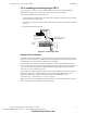
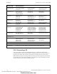
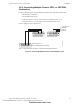
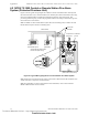
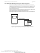
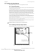
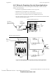
Table Of Contents
- Table of Contents
- Section 1 About This Manual
- Section 2 System Overview
- Section 3 Installation
- 3.1 Preparing for Installation
- 3.2 Installation Checklist
- 3.3 Mounting a Cabinet
- 3.4 Laying Out Equipment in Cabinet and Chassis
- 3.5 Installing the Control Panel
- 3.5.1 Control Panel Circuit Board & Keypad/Display Unit
- 3.5.2 Using NCA as Primary Display
- 3.5.3 Loop Expander Module
- 3.5.4 Network Control Module
- 3.5.5 Panel Circuit Modules and Other Option Boards
- 3.5.6 Overview
- 3.5.7 Connecting the Control Panel to AC Power
- 3.5.8 Checking AC Power
- 3.5.9 Installing and Connecting the Batteries
- 3.5.10 APS-6R Auxiliary Power Supply Connections
- 3.5.11 External DC Power Output Connections
- 3.5.12 NAC Connections & Releasing Circuits
- 3.5.13 Output Relay Connections
- 3.5.14 Backup-Alarm Switches
- 3.5.15 Installing a Transmitter Module TM-4
- 3.6 UL Power-limited Wiring Requirements
- 3.7 Installing Panel Circuit Modules
- 3.8 Auxiliary Relay Module (ARM-4): Product-Specific Details
- 3.9 Installing Remote Printers and/or CRT
- 3.10 Wiring a Signaling Line Circuit (SLC)
- Section 4 Applications
- Section 5 Testing the System
- Appendix A Power Supply Calculations
- Appendix B Electrical Specifications
- Appendix C Compatible Equipment
- Appendix D Canadian Applications
- Index

Fire/Security Applications Applications
NFS-640 Installation Manual P/N 51332:B2 07/27/2004 59
4.4.3 Receiving Unit
For applications requiring transmission of security alarm information to a central receiving unit, the
control panel may be connected via a UDACT to a compatible receiving unit (see the UDACT
Manual). For information on configuring the Receiving unit for Combination Fire/Security
applications, refer to the documentation for that control panel.
4.4.4 Programming
The control panel can communicate with any number of security devices. To do so, program the
points as follows:
1. Select the address of the module(s) to be used for security.
2. Select the Type Code
SECURITY.
Note: For detailed instruction on programming Type Codes, refer to the NFS-640 Programming
Manual.
Step Action
1 Install the STS-1 Tamper Switch onto the side of the backbox opposite the door hinge,
pushing the switch through the opening until it snaps into place.
2 Install the magnet on the same side of the cabinet door as the lock. Push the magnet
through the opening in the door until it snaps into place.
3 Connect the STS-1 connector to J10 (Tamper) on the Control Panel.
Technical Manuals Online! - http://www.tech-man.com
firealarmresources.com