
Instruction Manual
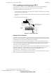
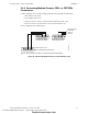
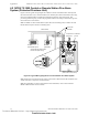
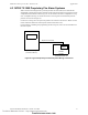
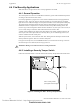
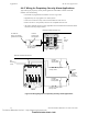
Table Of Contents
- Table of Contents
- Section 1 About This Manual
- Section 2 System Overview
- Section 3 Installation
- 3.1 Preparing for Installation
- 3.2 Installation Checklist
- 3.3 Mounting a Cabinet
- 3.4 Laying Out Equipment in Cabinet and Chassis
- 3.5 Installing the Control Panel
- 3.5.1 Control Panel Circuit Board & Keypad/Display Unit
- 3.5.2 Using NCA as Primary Display
- 3.5.3 Loop Expander Module
- 3.5.4 Network Control Module
- 3.5.5 Panel Circuit Modules and Other Option Boards
- 3.5.6 Overview
- 3.5.7 Connecting the Control Panel to AC Power
- 3.5.8 Checking AC Power
- 3.5.9 Installing and Connecting the Batteries
- 3.5.10 APS-6R Auxiliary Power Supply Connections
- 3.5.11 External DC Power Output Connections
- 3.5.12 NAC Connections & Releasing Circuits
- 3.5.13 Output Relay Connections
- 3.5.14 Backup-Alarm Switches
- 3.5.15 Installing a Transmitter Module TM-4
- 3.6 UL Power-limited Wiring Requirements
- 3.7 Installing Panel Circuit Modules
- 3.8 Auxiliary Relay Module (ARM-4): Product-Specific Details
- 3.9 Installing Remote Printers and/or CRT
- 3.10 Wiring a Signaling Line Circuit (SLC)
- Section 4 Applications
- Section 5 Testing the System
- Appendix A Power Supply Calculations
- Appendix B Electrical Specifications
- Appendix C Compatible Equipment
- Appendix D Canadian Applications
- Index

Applications Fire/Security Applications
58 NFS-640 Installation Manual P/N 51332:B2 07/27/2004
4.4 Fire/Security Applications
Note: NFS-640 is not approved for use in security applications in Canada.
4.4.1 General Operation
The control panel can be used as a combination Fire/Security system when installed and operated
according to the instructions in this section.
For security applications, program one or more monitor module (listed for security applications)
with the
SECURITY Type Code, and wire as shown in Figure 38. Activating this type of module
lights the
SECURITY LED, and displays a security alarm condition on the control panel LCD display.
The panel sounder will sound until the Security alarm is acknowledged. You can also program
additional sounders or output devices to activate with the security alarm initiating device. The
SECURITY Type Code is designed to indicate an alarm as follows: (a) on an open or short circuit; or
(b) on a ±50% change in resistance value from the End-of-Line resistor value.
A tamper switch installed in the cabinet door will indicate a door tamper condition whenever the
door is open. If the control panel indicates a Security alarm, you can acknowledge, silence, and
reset the condition from the control panel.
When the system resets, a 30-second exit timer starts. During this time the tamper switch and all
Security alarms are ignored. There is no entrance delay timer.
For bypass of security zones, use the DISABLE routine (covered in the Status Change section of
the NFS-640 Operations Manual) for Security type devices.
4.4.2 Installing a Security Tamper Switch
Follow the instructions below to wire the cabinet with a Security Tamper Switch kit model STS-1.
Figure 37 Installing the STS-1 Security Tamper Switch
!
WARNING: Damage can result from incorrect wiring connections.
nfs640-sts1.cdr
STS-1 mounting location
(side opposite of door hinges)
Connect to
J10 “Tamper”
Technical Manuals Online! - http://www.tech-man.com
firealarmresources.com