
Instruction Manual
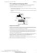
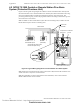
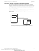
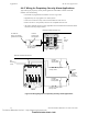
Table Of Contents
- Table of Contents
- Section 1 About This Manual
- Section 2 System Overview
- Section 3 Installation
- 3.1 Preparing for Installation
- 3.2 Installation Checklist
- 3.3 Mounting a Cabinet
- 3.4 Laying Out Equipment in Cabinet and Chassis
- 3.5 Installing the Control Panel
- 3.5.1 Control Panel Circuit Board & Keypad/Display Unit
- 3.5.2 Using NCA as Primary Display
- 3.5.3 Loop Expander Module
- 3.5.4 Network Control Module
- 3.5.5 Panel Circuit Modules and Other Option Boards
- 3.5.6 Overview
- 3.5.7 Connecting the Control Panel to AC Power
- 3.5.8 Checking AC Power
- 3.5.9 Installing and Connecting the Batteries
- 3.5.10 APS-6R Auxiliary Power Supply Connections
- 3.5.11 External DC Power Output Connections
- 3.5.12 NAC Connections & Releasing Circuits
- 3.5.13 Output Relay Connections
- 3.5.14 Backup-Alarm Switches
- 3.5.15 Installing a Transmitter Module TM-4
- 3.6 UL Power-limited Wiring Requirements
- 3.7 Installing Panel Circuit Modules
- 3.8 Auxiliary Relay Module (ARM-4): Product-Specific Details
- 3.9 Installing Remote Printers and/or CRT
- 3.10 Wiring a Signaling Line Circuit (SLC)
- Section 4 Applications
- Section 5 Testing the System
- Appendix A Power Supply Calculations
- Appendix B Electrical Specifications
- Appendix C Compatible Equipment
- Appendix D Canadian Applications
- Index

Applications NFPA 72-1999 Central or Remote Station Fire Alarm System (Protected Premises Unit)
56 NFS-640 Installation Manual P/N 51332:B2 07/27/2004
4.2 NFPA 72-1999 Central or Remote Station Fire Alarm
System (Protected Premises Unit)
Figure 35 shows typical wiring diagram for a NFPA 72-1999 Central Station Fire Alarm System
(Protected Premises Unit) or a Remote Station Fire Alarm System (Protected Premises Unit) using
the Universal Digital Alarm Communicator/Transmitter (UDACT) and control panel. This
provides typical wiring only; connect and program the UDACT according to the directions given in
the UDACT Instruction Manual.
Note: An NFPA 72-1999 Central Station requires 24 hours of standby power; an NFPA 72-1999
Remote Station requires 60 hours of standby power.
Figure 35 Typical Wiring Diagram for a Central Station Fire Alarm System
Note: Install a UL-listed 120 ohm End-of-Line resistor (P/N 71244) UDACT TB1 terminals 3 and
4 if this is the last or only device on EIA-485 line.
Note: This application can also be done with the TM-4 Transmitter; refer to the Transmitter
Module TM-4 document for more details.
TB13
EIA-485
+ ACS –
24V NONRST 24V RESET
+ – +
–
TB7
UDACT in ABS-8R
(shown with cover removed)
Solid earth
ground
To supervised
phone lines
Ferrite cores
P/N 29090
FACP Cabinet
EIA-485
(ACS Mode)
24 VDC
Nonresettable power
Supervised and power-limited
EIA-485 and power wiring
nfs640-udact.cdr
Technical Manuals Online! - http://www.tech-man.com
firealarmresources.com