
Instruction Manual
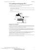
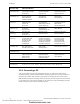
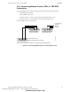
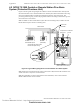
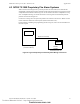
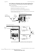
Table Of Contents
- Table of Contents
- Section 1 About This Manual
- Section 2 System Overview
- Section 3 Installation
- 3.1 Preparing for Installation
- 3.2 Installation Checklist
- 3.3 Mounting a Cabinet
- 3.4 Laying Out Equipment in Cabinet and Chassis
- 3.5 Installing the Control Panel
- 3.5.1 Control Panel Circuit Board & Keypad/Display Unit
- 3.5.2 Using NCA as Primary Display
- 3.5.3 Loop Expander Module
- 3.5.4 Network Control Module
- 3.5.5 Panel Circuit Modules and Other Option Boards
- 3.5.6 Overview
- 3.5.7 Connecting the Control Panel to AC Power
- 3.5.8 Checking AC Power
- 3.5.9 Installing and Connecting the Batteries
- 3.5.10 APS-6R Auxiliary Power Supply Connections
- 3.5.11 External DC Power Output Connections
- 3.5.12 NAC Connections & Releasing Circuits
- 3.5.13 Output Relay Connections
- 3.5.14 Backup-Alarm Switches
- 3.5.15 Installing a Transmitter Module TM-4
- 3.6 UL Power-limited Wiring Requirements
- 3.7 Installing Panel Circuit Modules
- 3.8 Auxiliary Relay Module (ARM-4): Product-Specific Details
- 3.9 Installing Remote Printers and/or CRT
- 3.10 Wiring a Signaling Line Circuit (SLC)
- Section 4 Applications
- Section 5 Testing the System
- Appendix A Power Supply Calculations
- Appendix B Electrical Specifications
- Appendix C Compatible Equipment
- Appendix D Canadian Applications
- Index

Installation Wiring a Signaling Line Circuit (SLC)
54 NFS-640 Installation Manual P/N 51332:B2 07/27/2004
3.10 Wiring a Signaling Line Circuit (SLC)
Overview
Communication between the control panel and intelligent and addressable initiating, monitor, and
control devices takes place through a Signaling Line Circuit (SLC). You can wire an SLC to meet
the requirements of NFPA Style 4, Style 6, or Style 7 circuits. This manual provides requirements
and performance details specific to this control panel; for installation information and general
information, refer to the SLC Wiring Manual.
Wiring
Maximum wiring distance of an SLC using 12 AWG (3.1 mm
2
) wire:
• Style 4 -12,500 feet (3810 meters) total twisted-pair.
• Style 6 & 7 -10,000 feet (3048 meters) total twisted-pair.
Capacity
The NFS-640 provides one (1) SLC, with a total capacity of 318 intelligent/addressable devices:
• 01-159 intelligent detectors
• 01-159 monitor and control modules
An optional expander board provides one (1) additional SLC, with the same capacity.
Installation
This control panel supports one or two SLC loops; a second SLC loop is obtained by installing an
LEM-320 module. SLC loop #1 connects to TB16 on the control panel; SLC loop #2 connects to
TB1 on the LEM-320. For details on designing, installing and configuring SLC loops, see the SLC
Wiring Manual.
Figure 34 SLC Loop Connections and Wiring
B+ A+ B- A- B+ A+ B- A-
T-Tapping is not allowed
on a four-wire SLC.
SLC B (output loop)
SLC A (loop return)
SLC B SLC A
Style 4 SLC Loops
Style 6 SLC Loops
TB1
B+ A+ B- A-
SLC1
B+ A+ B- A-
TB16
SLC Loop #2 Connections
on Loop Expander Module
SLC Loop #1 Connections
on FACP’s main circuit board
Use either
SLC Loop #1
or SLC Loop #2
nfs640-slcloops.cdr, nfs640-slc-tb.cdr, LEM320-slc-tb.cdr
Technical Manuals Online! - http://www.tech-man.com
firealarmresources.com