
Instruction Manual
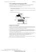
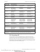
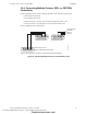
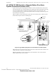
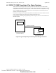
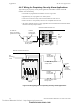
Table Of Contents
- Table of Contents
- Section 1 About This Manual
- Section 2 System Overview
- Section 3 Installation
- 3.1 Preparing for Installation
- 3.2 Installation Checklist
- 3.3 Mounting a Cabinet
- 3.4 Laying Out Equipment in Cabinet and Chassis
- 3.5 Installing the Control Panel
- 3.5.1 Control Panel Circuit Board & Keypad/Display Unit
- 3.5.2 Using NCA as Primary Display
- 3.5.3 Loop Expander Module
- 3.5.4 Network Control Module
- 3.5.5 Panel Circuit Modules and Other Option Boards
- 3.5.6 Overview
- 3.5.7 Connecting the Control Panel to AC Power
- 3.5.8 Checking AC Power
- 3.5.9 Installing and Connecting the Batteries
- 3.5.10 APS-6R Auxiliary Power Supply Connections
- 3.5.11 External DC Power Output Connections
- 3.5.12 NAC Connections & Releasing Circuits
- 3.5.13 Output Relay Connections
- 3.5.14 Backup-Alarm Switches
- 3.5.15 Installing a Transmitter Module TM-4
- 3.6 UL Power-limited Wiring Requirements
- 3.7 Installing Panel Circuit Modules
- 3.8 Auxiliary Relay Module (ARM-4): Product-Specific Details
- 3.9 Installing Remote Printers and/or CRT
- 3.10 Wiring a Signaling Line Circuit (SLC)
- Section 4 Applications
- Section 5 Testing the System
- Appendix A Power Supply Calculations
- Appendix B Electrical Specifications
- Appendix C Compatible Equipment
- Appendix D Canadian Applications
- Index

Installing Remote Printers and/or CRT Installation
NFS-640 Installation Manual P/N 51332:B2 07/27/2004 53
3.9.6 Connecting Multiple Printers, CRTs, or CRT/PRN
Combination
Connecting multiple devices requires changing the CRT-2 setup using the F1(Quick) menu:
• Set Host/Printer=EIA/AUX.
• Set EIA Data Format=8/1/N.
• If the AUX device is a printer, set the Printer and AUX Data Format=7/1/E.
• If the AUX device is a second CRT-2, set the AUX Data Format=8/1/N.
Connect multiple devices as shown below:
Figure 33 Connecting Multiple Devices on the EIA-232 Circuit
7 3 2
7 3 2
7 3 2
To Control Panel
TB15-REF
TB15-TX
TB15-RX
To EIA-232 port of CRT-2
(female socket shown)
To AUX Port of CRT-2
(female socket shown)
To EIA-232 port of next
CRT-2 or PRN (female socket shown)
prncrt-conn.cdr
Note: For wire requirements, see Table 16 in Appendix B “Electrical Specifications”.
Technical Manuals Online! - http://www.tech-man.com
firealarmresources.com