
Instruction Manual
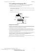
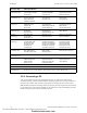
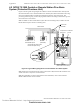
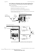
Table Of Contents
- Table of Contents
- Section 1 About This Manual
- Section 2 System Overview
- Section 3 Installation
- 3.1 Preparing for Installation
- 3.2 Installation Checklist
- 3.3 Mounting a Cabinet
- 3.4 Laying Out Equipment in Cabinet and Chassis
- 3.5 Installing the Control Panel
- 3.5.1 Control Panel Circuit Board & Keypad/Display Unit
- 3.5.2 Using NCA as Primary Display
- 3.5.3 Loop Expander Module
- 3.5.4 Network Control Module
- 3.5.5 Panel Circuit Modules and Other Option Boards
- 3.5.6 Overview
- 3.5.7 Connecting the Control Panel to AC Power
- 3.5.8 Checking AC Power
- 3.5.9 Installing and Connecting the Batteries
- 3.5.10 APS-6R Auxiliary Power Supply Connections
- 3.5.11 External DC Power Output Connections
- 3.5.12 NAC Connections & Releasing Circuits
- 3.5.13 Output Relay Connections
- 3.5.14 Backup-Alarm Switches
- 3.5.15 Installing a Transmitter Module TM-4
- 3.6 UL Power-limited Wiring Requirements
- 3.7 Installing Panel Circuit Modules
- 3.8 Auxiliary Relay Module (ARM-4): Product-Specific Details
- 3.9 Installing Remote Printers and/or CRT
- 3.10 Wiring a Signaling Line Circuit (SLC)
- Section 4 Applications
- Section 5 Testing the System
- Appendix A Power Supply Calculations
- Appendix B Electrical Specifications
- Appendix C Compatible Equipment
- Appendix D Canadian Applications
- Index

Installing Remote Printers and/or CRT Installation
NFS-640 Installation Manual P/N 51332:B2 07/27/2004 51
3.9.4 Installing and Configuring a CRT-2
A CRT-2 can only be used in a non-networked application when used with the NFS-640. For
further details on setting up the CRT-2, refer to the NFS-640 Operations Manual.
Connect a CRT-2 to the Control Panel as follows:
1. Connect the three (3) open leads of the custom cable to the TB15 terminal block on the control
panel as shown in the figure below.
2. Plug the DB-25 connector end of the custom cable into the EIA-232 port of the CRT-2. Tighten
securely.
3. Set parameters as discussed below.
Figure 32 Connecting a CRT-2
Setting CRT-2 Parameters
The CRT-2 communicates with the control panel through a protocol defined by thirteen groups of
parameters. To access a parameter group, press the corresponding function key (F1-F12) as shown
in Table 8 below. You can then program parameters in each group.
Enter the CRT-2 setup menu by pressing and holding the <Ctrl> key while pressing the <Scroll
Lock> key. Use arrow keys to move through the selections in each setup group; press the space bar
to view the options for each parameter. When finished programming all setup groups, press the
<Pause> key. To save all changes, press <Y>.
Table 8 shows the standard settings for using the CRT-2 with the NFS-640; for one instance where
these settings may change slightly see Section 3.9.6 “Connecting Multiple Printers, CRTs, or
CRT/PRN Combination”. The basic settings for using the CRT-2 with NFS-640 are:
• Baud Rate 9600 • Data format 8 1 N • Protocol xon/off.
Note: This section covers installation only; for information on how the CRT-2 functions as part of
the fire alarm system, see the NFS-640 Operations Manual.
TB14 TB15
PRINTER
TX RX REF
PC/CRT
TX RX REF
DB-25 connector
on CRT-2 (female
socket shown)
Control
Panel
nfs640-crt2conn.cdr
Terminate one end of
shield at backbox
Technical Manuals Online! - http://www.tech-man.com
firealarmresources.com