
Instruction Manual
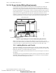
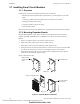
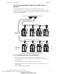
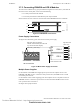
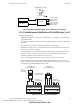
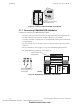
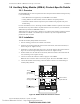
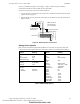
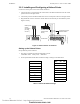
Table Of Contents
- Table of Contents
- Section 1 About This Manual
- Section 2 System Overview
- Section 3 Installation
- 3.1 Preparing for Installation
- 3.2 Installation Checklist
- 3.3 Mounting a Cabinet
- 3.4 Laying Out Equipment in Cabinet and Chassis
- 3.5 Installing the Control Panel
- 3.5.1 Control Panel Circuit Board & Keypad/Display Unit
- 3.5.2 Using NCA as Primary Display
- 3.5.3 Loop Expander Module
- 3.5.4 Network Control Module
- 3.5.5 Panel Circuit Modules and Other Option Boards
- 3.5.6 Overview
- 3.5.7 Connecting the Control Panel to AC Power
- 3.5.8 Checking AC Power
- 3.5.9 Installing and Connecting the Batteries
- 3.5.10 APS-6R Auxiliary Power Supply Connections
- 3.5.11 External DC Power Output Connections
- 3.5.12 NAC Connections & Releasing Circuits
- 3.5.13 Output Relay Connections
- 3.5.14 Backup-Alarm Switches
- 3.5.15 Installing a Transmitter Module TM-4
- 3.6 UL Power-limited Wiring Requirements
- 3.7 Installing Panel Circuit Modules
- 3.8 Auxiliary Relay Module (ARM-4): Product-Specific Details
- 3.9 Installing Remote Printers and/or CRT
- 3.10 Wiring a Signaling Line Circuit (SLC)
- Section 4 Applications
- Section 5 Testing the System
- Appendix A Power Supply Calculations
- Appendix B Electrical Specifications
- Appendix C Compatible Equipment
- Appendix D Canadian Applications
- Index

Installation Installing Remote Printers and/or CRT
50 NFS-640 Installation Manual P/N 51332:B2 07/27/2004
3.9.3 Installing and Configuring a Keltron Printer
Connect the remote printer to the Control Panel as follows:
1. Connect the three (3) open leads of the custom cable to the TB14 terminal block on the control
panel as shown in the figure below.
2. Connect DC power from TB7 terminal block on the control panel as shown in the figure below.
3. Plug the DB-25 connector end of the custom cable into the EIA-232 port of the Keltron printer.
Tighten securely.
Figure 31 Keltron Printer Connections
Setting up the Keltron Printer
Set up a Keltron printer as follows:
1. The printer communicates using the following protocol:
• Baud Rate: 9600 • Parity: Even • Data bits: 7
2. Set the printer DIP switches SP1 and SP2 according to settings in the table below:
Table 7 Keltron DIP Switch Settings
TB14 TB15
PRINTER
TX RX REF
PC/CRT
TX RX REF
24V 24V NONRST RESET
+ – +
–
TB7
nfs640-keltconn.cdr
DB-25 connector
on Keltron Printer
(female socket
shown)
Keltron printer
24 VDC
connections
(14 AWG,
2.00 mm
2
)
Control Panel
Terminate one end of
shield at backbox
SP1 On Off
1X
2X
3X
4X
5X
6X
7X
8X
SP2 On Off
1X
2X
3X
4X
5X
6X
7X
8X
Technical Manuals Online! - http://www.tech-man.com
firealarmresources.com