
Instruction Manual
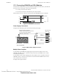
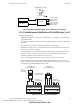
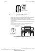
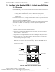
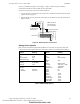
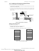
Table Of Contents
- Table of Contents
- Section 1 About This Manual
- Section 2 System Overview
- Section 3 Installation
- 3.1 Preparing for Installation
- 3.2 Installation Checklist
- 3.3 Mounting a Cabinet
- 3.4 Laying Out Equipment in Cabinet and Chassis
- 3.5 Installing the Control Panel
- 3.5.1 Control Panel Circuit Board & Keypad/Display Unit
- 3.5.2 Using NCA as Primary Display
- 3.5.3 Loop Expander Module
- 3.5.4 Network Control Module
- 3.5.5 Panel Circuit Modules and Other Option Boards
- 3.5.6 Overview
- 3.5.7 Connecting the Control Panel to AC Power
- 3.5.8 Checking AC Power
- 3.5.9 Installing and Connecting the Batteries
- 3.5.10 APS-6R Auxiliary Power Supply Connections
- 3.5.11 External DC Power Output Connections
- 3.5.12 NAC Connections & Releasing Circuits
- 3.5.13 Output Relay Connections
- 3.5.14 Backup-Alarm Switches
- 3.5.15 Installing a Transmitter Module TM-4
- 3.6 UL Power-limited Wiring Requirements
- 3.7 Installing Panel Circuit Modules
- 3.8 Auxiliary Relay Module (ARM-4): Product-Specific Details
- 3.9 Installing Remote Printers and/or CRT
- 3.10 Wiring a Signaling Line Circuit (SLC)
- Section 4 Applications
- Section 5 Testing the System
- Appendix A Power Supply Calculations
- Appendix B Electrical Specifications
- Appendix C Compatible Equipment
- Appendix D Canadian Applications
- Index

Installing Remote Printers and/or CRT Installation
NFS-640 Installation Manual P/N 51332:B2 07/27/2004 49
may use your building emergency power supply, so long as it meets the power continuity
requirements of NFPA 72. Refer to NFPA 72 for further details.
Connect the remote printer to the Control Panel as follows:
1. Connect the three (3) open leads of the custom cable to the TB14 terminal block on the control
panel as shown in Figure 30.
2. Plug the DB-25 connector end of the custom cable into the EIA-232 port of the remote printer.
Tighten securely.
Figure 30 Remote Printer Connections
Setting Printer Options
Refer to the documentation supplied with the PRN-5 for instructions on using the printer menu
controls. Set the printer options (under the menu area) according to the settings listed in Table 6.
TB14 TB15
PRINTER
TX RX REF
PC/CRT
TX RX REF
Note: Outputs are
power-limited but
are not supervised.
nfs640-prn5conn.cdr
DB-25 connector
on PRN-5 (female
socket shown)
Control Panel
Terminate one end of
shield at backbox
Option Setting Option Setting
Font
LPI
ESC Character
Bidirectional Copy
HS Draft
6 LPI
ESC
ON
CPI
Skip
Emulate
I/O
Buffer
Serial
Baud
Format
Protocol
Character Set
Sl.Zero
Auto LF
PAPER
BIN 1
BIN 2
SINGLE
PUSH TRA
PULL TRA
PAP ROLL
10 CPI
0.5
Epson FX-850
40K
9600 or 2400
7 Bit, Even, 1 Stop
XON/XOFF
Standard
On
Off
12/72"
12/72"
12/72"
12/72"
12/72"
12/72"
CG-TAB
Country
Auto CR
Graphic
E-US ASCII
OFF
Color Option
Formlen
Lines
Standard
Not Installed
6LPI=60
Exec 10.5
Table 6 PRN-5 Setup Options
Technical Manuals Online! - http://www.tech-man.com
firealarmresources.com