
Instruction Manual
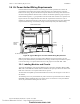
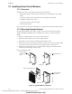
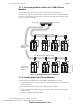
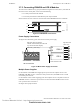
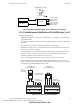
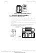
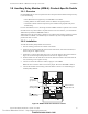
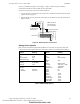
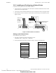
Table Of Contents
- Table of Contents
- Section 1 About This Manual
- Section 2 System Overview
- Section 3 Installation
- 3.1 Preparing for Installation
- 3.2 Installation Checklist
- 3.3 Mounting a Cabinet
- 3.4 Laying Out Equipment in Cabinet and Chassis
- 3.5 Installing the Control Panel
- 3.5.1 Control Panel Circuit Board & Keypad/Display Unit
- 3.5.2 Using NCA as Primary Display
- 3.5.3 Loop Expander Module
- 3.5.4 Network Control Module
- 3.5.5 Panel Circuit Modules and Other Option Boards
- 3.5.6 Overview
- 3.5.7 Connecting the Control Panel to AC Power
- 3.5.8 Checking AC Power
- 3.5.9 Installing and Connecting the Batteries
- 3.5.10 APS-6R Auxiliary Power Supply Connections
- 3.5.11 External DC Power Output Connections
- 3.5.12 NAC Connections & Releasing Circuits
- 3.5.13 Output Relay Connections
- 3.5.14 Backup-Alarm Switches
- 3.5.15 Installing a Transmitter Module TM-4
- 3.6 UL Power-limited Wiring Requirements
- 3.7 Installing Panel Circuit Modules
- 3.8 Auxiliary Relay Module (ARM-4): Product-Specific Details
- 3.9 Installing Remote Printers and/or CRT
- 3.10 Wiring a Signaling Line Circuit (SLC)
- Section 4 Applications
- Section 5 Testing the System
- Appendix A Power Supply Calculations
- Appendix B Electrical Specifications
- Appendix C Compatible Equipment
- Appendix D Canadian Applications
- Index

Installation Installing Remote Printers and/or CRT
48 NFS-640 Installation Manual P/N 51332:B2 07/27/2004
3.8.3 Field Wiring an Auxiliary Relay Module
The figure above shows terminal assignments for ARM-4 module control relays K1-K4, which
control nonpower-limited circuits. Power-limited and nonpower-limited circuit wiring must remain
separated by at least 0.25 inch (6.35 mm) within the cabinet and exit the cabinet though different
knockouts, conduits, or both.
Note: For more information, refer to Section 3.6 “UL Power-limited Wiring Requirements”.
The table contains contact ratings for relays K1-K4 on the ARM-4 module:
3.9 Installing Remote Printers and/or CRT
3.9.1 Custom Cable Fabrication
A custom cable needs to be fabricated to connect the PRN-5 Printer, Keltron Printer or the CRT-2
Monitor to the system. Length of the cable will vary with each installation, but should not exceed a
maximum length of 50 feet (15.24 meters). Printer must be installed in the same room as panel.
Construct cable as follows:
1. Using overall foil/braided-shield twisted-pair cable, properly connect one end to the DB-25
Connector using the wiring specifications shown in the table below. (Custom cable kit P/N
90106 is provided.)
2. Tighten clamp on connector to secure cable.
3.9.2 Installing and Configuring the PRN-5 Printer
When connected to the Control Panel via an EIA-232 interface, the PRN-5 prints a copy of all
status changes within the control panel and time-stamps the printout with the time of day and date
the event occurred. It provides 80 columns of data on standard 9" by 11" tractor-feed paper.
Note: You can also use the EIA-232 printer interface with UL-listed I.T.E. equipment, such as
personal computers, to monitor the control panel for supplementary purposes.
This section contains information on connecting a printer to the control panel and for setting the
printer options.
Connecting a Remote PRN Printer
Remote printers require a 120 VAC, 50/60 Hz primary power source. If required for the fire alarm
system configuration (for example, a Proprietary Fire Alarm System), a remote printer requires a
secondary power source (battery backup). Because a secondary power source is not provided, use a
separate Uninterruptable Power Supply (UPS) that is UL-listed for Fire Protective Signaling. You
Resistive Load
Contacts
Normally Open (N.O.) Normally Closed (N.C.)
125 VAC 20 A 10 A
30 VDC 20 A 10 A
Table 5 Contact Ratings for K1-K4 on the ARM-4 Module
DB-25 Connector
(Custom cable kit 90106) TB14 on Control Panel
Pin 3 TX
Pin 2 RX
Pin 7 REF
Technical Manuals Online! - http://www.tech-man.com
firealarmresources.com