
Instruction Manual
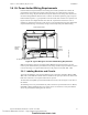
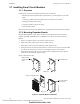
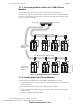
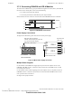
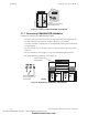
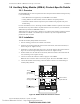
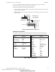
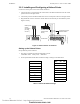
Table Of Contents
- Table of Contents
- Section 1 About This Manual
- Section 2 System Overview
- Section 3 Installation
- 3.1 Preparing for Installation
- 3.2 Installation Checklist
- 3.3 Mounting a Cabinet
- 3.4 Laying Out Equipment in Cabinet and Chassis
- 3.5 Installing the Control Panel
- 3.5.1 Control Panel Circuit Board & Keypad/Display Unit
- 3.5.2 Using NCA as Primary Display
- 3.5.3 Loop Expander Module
- 3.5.4 Network Control Module
- 3.5.5 Panel Circuit Modules and Other Option Boards
- 3.5.6 Overview
- 3.5.7 Connecting the Control Panel to AC Power
- 3.5.8 Checking AC Power
- 3.5.9 Installing and Connecting the Batteries
- 3.5.10 APS-6R Auxiliary Power Supply Connections
- 3.5.11 External DC Power Output Connections
- 3.5.12 NAC Connections & Releasing Circuits
- 3.5.13 Output Relay Connections
- 3.5.14 Backup-Alarm Switches
- 3.5.15 Installing a Transmitter Module TM-4
- 3.6 UL Power-limited Wiring Requirements
- 3.7 Installing Panel Circuit Modules
- 3.8 Auxiliary Relay Module (ARM-4): Product-Specific Details
- 3.9 Installing Remote Printers and/or CRT
- 3.10 Wiring a Signaling Line Circuit (SLC)
- Section 4 Applications
- Section 5 Testing the System
- Appendix A Power Supply Calculations
- Appendix B Electrical Specifications
- Appendix C Compatible Equipment
- Appendix D Canadian Applications
- Index

Auxiliary Relay Module (ARM-4): Product-Specific Details Installation
NFS-640 Installation Manual P/N 51332:B2 07/27/2004 47
3.8 Auxiliary Relay Module (ARM-4): Product-Specific Details
3.8.1 Overview
If a CRM-4RK/CRE-4 is to be incorporated into the control panel and an ARM-4 is being driven by
it, note the following:
• Each ARM-4 must be supported by one CRM-4RK or one CRE-4.
• If using ARM-4’s for both modules, mount two ARM-4’s in separate positions.
• If mounted in FACP enclosure keep all non-power limited wiring separate from power
limited wiring.
For ease of installation, service, and wiring mount the ARM-4 module in a position on the chassis
that will not have any other module or expander board in front of it. However, you can install the
ARM-4 directly behind the CRM-4RK or CRE-4.
ARM-4 mounts in the second, third or fourth row of a CAB-4 series backbox, against the back of a
chassis CHS-4 or CHS-4L. The ARM-4 may be mounted in any of the 8 adjacent backbox
positions the cable can reach.
3.8.2 Installation
To install the Auxiliary Relay Module in the chassis:
1. Select a mounting position for the module on the chassis.
2. Install two (2) mounting stand-offs onto the studs of the chassis, at the selected location, as
shown in Figure 12. Tighten securely.
3. Install three (3) support stand-offs, with screws, onto the PC board in the locations shown in
Figure 12 or in the two right-hand positions on the first row. Tighten securely.
4. Position module over the stand-offs on the chassis; fasten the module to the chassis with the
two (2) retaining screws. Tighten securely.
5. Connect one end of the Cable (P/N 71092) to plug P1 on the ARM-4.
Note: The other end of the cable is connected to jumper JP5 on the CRM-4RK or CRE-4.
6. Connect all available external wiring at this time. Refer to Section 3.8.3 “Field Wiring an
Auxiliary Relay Module”.
Figure 29 ARM-4 Stand-off & Terminal Locations
P2
P1
NC NO C
NC NO C
NC NO C
NC NO C
Com K1 K2 K3 K4
– + + + +
ARM-4.cdr
P-1
Connection for
Cable P/N 71092
These 3 holes for
support stand-offs.
These 2 holes for
mounting stand-offs.
Terminal
Assignments
(typ. 4 places)
Technical Manuals Online! - http://www.tech-man.com
firealarmresources.com