
Instruction Manual
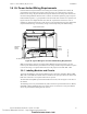
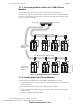
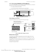
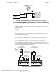
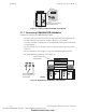
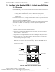
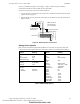
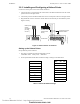
Table Of Contents
- Table of Contents
- Section 1 About This Manual
- Section 2 System Overview
- Section 3 Installation
- 3.1 Preparing for Installation
- 3.2 Installation Checklist
- 3.3 Mounting a Cabinet
- 3.4 Laying Out Equipment in Cabinet and Chassis
- 3.5 Installing the Control Panel
- 3.5.1 Control Panel Circuit Board & Keypad/Display Unit
- 3.5.2 Using NCA as Primary Display
- 3.5.3 Loop Expander Module
- 3.5.4 Network Control Module
- 3.5.5 Panel Circuit Modules and Other Option Boards
- 3.5.6 Overview
- 3.5.7 Connecting the Control Panel to AC Power
- 3.5.8 Checking AC Power
- 3.5.9 Installing and Connecting the Batteries
- 3.5.10 APS-6R Auxiliary Power Supply Connections
- 3.5.11 External DC Power Output Connections
- 3.5.12 NAC Connections & Releasing Circuits
- 3.5.13 Output Relay Connections
- 3.5.14 Backup-Alarm Switches
- 3.5.15 Installing a Transmitter Module TM-4
- 3.6 UL Power-limited Wiring Requirements
- 3.7 Installing Panel Circuit Modules
- 3.8 Auxiliary Relay Module (ARM-4): Product-Specific Details
- 3.9 Installing Remote Printers and/or CRT
- 3.10 Wiring a Signaling Line Circuit (SLC)
- Section 4 Applications
- Section 5 Testing the System
- Appendix A Power Supply Calculations
- Appendix B Electrical Specifications
- Appendix C Compatible Equipment
- Appendix D Canadian Applications
- Index

Installing Panel Circuit Modules Installation
NFS-640 Installation Manual P/N 51332:B2 07/27/2004 45
Figure 25 Sample ICM-4RK Configuration for Multiple Power Supplies
3.7.6 Field-Wiring the ICM-4RK and ICE-4 (NFPA Style Y or Z)
Guidelines for field-wiring:
• Notification Appliance Circuits (NACs) are supervised, power-limited, and can connect to an
energy-limited cable.
• Use only the compatible, UL-listed notification appliances listed in the Device Compatibility
Document.
• Wire notification appliances according to the manufacturer's instructions.
• Maximum current per circuit is 3.0 A. Maximum current per module depends on the type of
power supply (standard or auxiliary).
• Canadian installations require model N-ELR End-of-Line Resistor Assembly (Style Y only).
• Size NAC wiring so the voltage drop does not exceed the minimum rated voltage of the
notification appliance used as the last device on the circuit.
• For zone coded applications, refer to the UZC-256 Universal Zone Coder manual.
• The ICM-4RK is California Code programmable (microprocessor P/N 34077 Rev. B or
higher). To program for California Code, cut diode D35 as shown in Figure 27. (See appendix
section of the Programming Manual for more detail.)
Figure 26 Field-Wiring an ICM-4RK/ICE-4
ICM-4RK/ICE-4 Jumpers
APS-6R #1
APS-6R #2
J6
J5
JP1
JP2
ICM-4RK
J6
J5
Two circuits that
share 3 A of one
AVPS-24 (#1)
Two circuits that
share 3 A of one
AVPS-24 (#2)
B+ A+ A– B– B+ A+ A– B– B+ A+ A– B– B+ A+ A– B–
Jumpers for
unused circuits
4.7K,
1/2 watt ELR
P/N 71252
UL-listed 24 VDC
Polarized Devices
ICM4wire-YB.cdr
Typical NFPA
Style Z (Class A) NAC
Typical NFPA
Style Y (Class B) NAC
Jumpers for
unused circuits
Technical Manuals Online! - http://www.tech-man.com
firealarmresources.com