
Instruction Manual
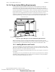
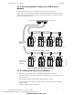
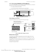
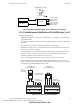
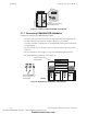
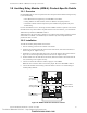
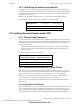
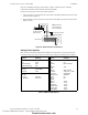
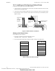
Table Of Contents
- Table of Contents
- Section 1 About This Manual
- Section 2 System Overview
- Section 3 Installation
- 3.1 Preparing for Installation
- 3.2 Installation Checklist
- 3.3 Mounting a Cabinet
- 3.4 Laying Out Equipment in Cabinet and Chassis
- 3.5 Installing the Control Panel
- 3.5.1 Control Panel Circuit Board & Keypad/Display Unit
- 3.5.2 Using NCA as Primary Display
- 3.5.3 Loop Expander Module
- 3.5.4 Network Control Module
- 3.5.5 Panel Circuit Modules and Other Option Boards
- 3.5.6 Overview
- 3.5.7 Connecting the Control Panel to AC Power
- 3.5.8 Checking AC Power
- 3.5.9 Installing and Connecting the Batteries
- 3.5.10 APS-6R Auxiliary Power Supply Connections
- 3.5.11 External DC Power Output Connections
- 3.5.12 NAC Connections & Releasing Circuits
- 3.5.13 Output Relay Connections
- 3.5.14 Backup-Alarm Switches
- 3.5.15 Installing a Transmitter Module TM-4
- 3.6 UL Power-limited Wiring Requirements
- 3.7 Installing Panel Circuit Modules
- 3.8 Auxiliary Relay Module (ARM-4): Product-Specific Details
- 3.9 Installing Remote Printers and/or CRT
- 3.10 Wiring a Signaling Line Circuit (SLC)
- Section 4 Applications
- Section 5 Testing the System
- Appendix A Power Supply Calculations
- Appendix B Electrical Specifications
- Appendix C Compatible Equipment
- Appendix D Canadian Applications
- Index

Installation Installing Panel Circuit Modules
44 NFS-640 Installation Manual P/N 51332:B2 07/27/2004
3.7.5 Connecting ICM-4RK and ICE-4 Modules
The total current available for any group of Notification Appliance Circuits (NACs), other than the
four NACs on the control panel, cannot exceed the following:
• 6.0 A when powered from the APS-6R
• 1.25 A when powered from a NFS-640 DC power output terminal
Shown below are the wire connectors on the bottom of the ICM-4RK and the ICE-4 modules.
Figure 23 ICM-4RK/ICE-4 Connectors
Power Supply Connections
The figure below illustrates typical connections from main power supply.
Figure 24 Main Power Supply Connection
Multiple Power Supplies
Cut JP1 and JP2 on ICM-4RK when supplying 24V power from two separate sources to the
ICM-4RK. ICM-4RK circuits 1-2 will receive their power from J5; ICM-4RK circuits 3-4 will
receive their power from J6.
Cut JP1 and JP2 on ICE-4 when supplying power from separate sources to expander circuits 5-8.
ICM-4RK circuits 5-6 will receive power from J5 on the ICE-4 and ICM-4RK circuits 7-8 will
receive power from J6 on the ICE-4.
See Figure 25 for jumper locations.
nfs640-icmconn.cdr
ICM-4RK
ICE-4
J5
J6
J5
J6
J5
ICM-4
J6
ICE-4
J5
TB7
24V 24V RESETNONRST
+ – + –
Power Cable P/N 71091
nfs640-icmnac.cdr
Eight NACs that
share 1.25 A
TB7 on Control Panel
Bell power cable (P/N 75400) or
alternate Power Harness (P/N 71093, with
lugs removed and wires stripped)
Black wire (–), Blue wire (+)
Technical Manuals Online! - http://www.tech-man.com
firealarmresources.com