
Instruction Manual
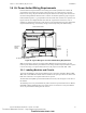
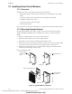
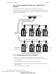
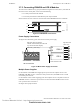
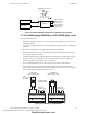
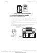
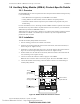
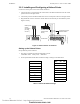
Table Of Contents
- Table of Contents
- Section 1 About This Manual
- Section 2 System Overview
- Section 3 Installation
- 3.1 Preparing for Installation
- 3.2 Installation Checklist
- 3.3 Mounting a Cabinet
- 3.4 Laying Out Equipment in Cabinet and Chassis
- 3.5 Installing the Control Panel
- 3.5.1 Control Panel Circuit Board & Keypad/Display Unit
- 3.5.2 Using NCA as Primary Display
- 3.5.3 Loop Expander Module
- 3.5.4 Network Control Module
- 3.5.5 Panel Circuit Modules and Other Option Boards
- 3.5.6 Overview
- 3.5.7 Connecting the Control Panel to AC Power
- 3.5.8 Checking AC Power
- 3.5.9 Installing and Connecting the Batteries
- 3.5.10 APS-6R Auxiliary Power Supply Connections
- 3.5.11 External DC Power Output Connections
- 3.5.12 NAC Connections & Releasing Circuits
- 3.5.13 Output Relay Connections
- 3.5.14 Backup-Alarm Switches
- 3.5.15 Installing a Transmitter Module TM-4
- 3.6 UL Power-limited Wiring Requirements
- 3.7 Installing Panel Circuit Modules
- 3.8 Auxiliary Relay Module (ARM-4): Product-Specific Details
- 3.9 Installing Remote Printers and/or CRT
- 3.10 Wiring a Signaling Line Circuit (SLC)
- Section 4 Applications
- Section 5 Testing the System
- Appendix A Power Supply Calculations
- Appendix B Electrical Specifications
- Appendix C Compatible Equipment
- Appendix D Canadian Applications
- Index

Installing Panel Circuit Modules Installation
NFS-640 Installation Manual P/N 51332:B2 07/27/2004 43
3.7.3 Connecting Ribbon Cables for a CAB-4 Series
Backbox
Expander Row Ribbon Cables connect panel circuit modules to the Control Panel.
Figure 22 shows a typical wiring setup using two Expander Row Ribbon Cables (P/N 71088) to
connect the control panel to two rows of four (4) panel circuit modules each below the Control
Panel in a CAB-4 Series backbox.
Figure 22 Expander Row Ribbon Cable Setup
3.7.4 Installing the Panel Circuit Modules
To install a panel circuit module such as a ICM-4RK or CRM-4RK into the chassis:
1. Angle the module into the chassis so that the lower board edge slips into the chassis slots as
shown in Figure 11.
2. Push the upper end of the module into the upper opening in the chassis.
3. Secure the module to the chassis with the two module screws (provided with the module).
Tighten securely.
4. Connect the Ribbon Cable to the module.
MODUL E
TYPE
LAMP S
SWITCH
MODUL E
TYPE
LAMP S
SWITCH
MODUL E
TYPE
LAMP S
SWITCH
MODUL E
TYPE
LAMP S
SWITCH
MODUL E
TYPE
LAMP S
SWITCH
MODUL E
TYPE
LAMP S
SWITCH
MOD UL E
TYPE
LAMP S
SWITCH
MODUL E
TYPE
LAMP S
SWITCH
MODUL E
TYPE
LAMP S
SWITCH
MODUL E
TYPE
LAMP S
SWITCH
MODUL E
TYPE
LAMP S
SWITCH
MODUL E
TYPE
LAMP S
SWITCH
MODUL E
TYPE
LAMP S
SWITCH
MODUL E
TYPE
LAMP S
SWITCH
MOD UL E
TYPE
LAMP S
SWITCH
MODUL E
TYPE
LAMP S
SWITCH
P1.1–P1.8 P2.1–P2.8 P3.1–P3.8 P4.1–P4.8
nfs640-icmribbon.cdr
Expander Row Ribbon Cable (P/N 71088)
Expander Row Ribbon Cable (P/N 71088)
Group of panel
modules in third
cabinet row
J5 - Second Row
P5.1–P5.8 P6.1–P6.8 P7.1–P7.8 P8.1–P8.8
J6 - Third Row
Group of panel
modules in second
cabinet row
Technical Manuals Online! - http://www.tech-man.com
firealarmresources.com