
Instruction Manual
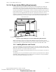
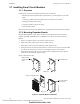
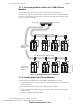
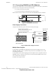
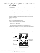
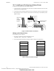
Table Of Contents
- Table of Contents
- Section 1 About This Manual
- Section 2 System Overview
- Section 3 Installation
- 3.1 Preparing for Installation
- 3.2 Installation Checklist
- 3.3 Mounting a Cabinet
- 3.4 Laying Out Equipment in Cabinet and Chassis
- 3.5 Installing the Control Panel
- 3.5.1 Control Panel Circuit Board & Keypad/Display Unit
- 3.5.2 Using NCA as Primary Display
- 3.5.3 Loop Expander Module
- 3.5.4 Network Control Module
- 3.5.5 Panel Circuit Modules and Other Option Boards
- 3.5.6 Overview
- 3.5.7 Connecting the Control Panel to AC Power
- 3.5.8 Checking AC Power
- 3.5.9 Installing and Connecting the Batteries
- 3.5.10 APS-6R Auxiliary Power Supply Connections
- 3.5.11 External DC Power Output Connections
- 3.5.12 NAC Connections & Releasing Circuits
- 3.5.13 Output Relay Connections
- 3.5.14 Backup-Alarm Switches
- 3.5.15 Installing a Transmitter Module TM-4
- 3.6 UL Power-limited Wiring Requirements
- 3.7 Installing Panel Circuit Modules
- 3.8 Auxiliary Relay Module (ARM-4): Product-Specific Details
- 3.9 Installing Remote Printers and/or CRT
- 3.10 Wiring a Signaling Line Circuit (SLC)
- Section 4 Applications
- Section 5 Testing the System
- Appendix A Power Supply Calculations
- Appendix B Electrical Specifications
- Appendix C Compatible Equipment
- Appendix D Canadian Applications
- Index

Installation Installing Panel Circuit Modules
42 NFS-640 Installation Manual P/N 51332:B2 07/27/2004
3.7 Installing Panel Circuit Modules
3.7.1 Overview
Installation of a panel circuit module is divided into five (5) operations:
• Mounting an optional expander board to the module (e.g. mounting ICE-4 onto an ICM-
4RK).
• Connecting communication ribbon cables from Control Panel to the module.
• Installing the module onto a chassis.
• Connecting modules to the power supply.
• Field wiring the module.
Refer to Section 2.10 “Panel Circuit Modules” for a complete list of modules and their expanders.
3.7.2 Mounting Expander Boards
Expander Board Modules, such as ICE-4 or CRE-4, need to be mounted onto their respective
modules (ICM-4RK, CRM-4RK) prior to installation onto a chassis. To mount an Expander
Module:
1. Remove one module support screw and set it aside for later use.
2. Replace the module support screw with one module stand-off.
3. Repeat Steps 1 and 2 for the three remaining module support screws.
4. Insert pins on the front of the expander board into connector on the back of the module. Make
sure the pins are in line; then, press the two units together until they snap into place.
5. Install the four module support screws (removed earlier) through the back of the expander
board and into the stand-offs. Tighten securely.
Figure 21 illustrates the steps.
Figure 21 Expander Module Installation
Install module stand-
off
Remove existing
module support
screw
Plug in the expander board
Secure with module
support screws
nfs640-pcmods.cdr
Steps 1 & 2
Steps 4 & 5
Technical Manuals Online! - http://www.tech-man.com
firealarmresources.com