
Instruction Manual
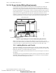
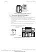
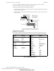
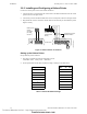
Table Of Contents
- Table of Contents
- Section 1 About This Manual
- Section 2 System Overview
- Section 3 Installation
- 3.1 Preparing for Installation
- 3.2 Installation Checklist
- 3.3 Mounting a Cabinet
- 3.4 Laying Out Equipment in Cabinet and Chassis
- 3.5 Installing the Control Panel
- 3.5.1 Control Panel Circuit Board & Keypad/Display Unit
- 3.5.2 Using NCA as Primary Display
- 3.5.3 Loop Expander Module
- 3.5.4 Network Control Module
- 3.5.5 Panel Circuit Modules and Other Option Boards
- 3.5.6 Overview
- 3.5.7 Connecting the Control Panel to AC Power
- 3.5.8 Checking AC Power
- 3.5.9 Installing and Connecting the Batteries
- 3.5.10 APS-6R Auxiliary Power Supply Connections
- 3.5.11 External DC Power Output Connections
- 3.5.12 NAC Connections & Releasing Circuits
- 3.5.13 Output Relay Connections
- 3.5.14 Backup-Alarm Switches
- 3.5.15 Installing a Transmitter Module TM-4
- 3.6 UL Power-limited Wiring Requirements
- 3.7 Installing Panel Circuit Modules
- 3.8 Auxiliary Relay Module (ARM-4): Product-Specific Details
- 3.9 Installing Remote Printers and/or CRT
- 3.10 Wiring a Signaling Line Circuit (SLC)
- Section 4 Applications
- Section 5 Testing the System
- Appendix A Power Supply Calculations
- Appendix B Electrical Specifications
- Appendix C Compatible Equipment
- Appendix D Canadian Applications
- Index

UL Power-limited Wiring Requirements Installation
NFS-640 Installation Manual P/N 51332:B2 07/27/2004 41
3.6 UL Power-limited Wiring Requirements
Power-limited and nonpower-limited circuit wiring must remain separated in the cabinet. All
power-limited circuit wiring must remain at least 0.25 inches (6.35 mm) from any nonpower-
limited circuit wiring. All power-limited and nonpower-limited circuit wiring must enter and exit
the cabinet through different knockout and or conduits. To maintain separation, group non-power
limited modules together, i.e., group modules on the same side of the enclosure or in separate rows.
Figure 20 shows one configuration that meets these UL requirements. The first two rows of
modules are configured with at least a 0.25 inch (6.35 mm) separation between power-limited and
nonpower-limited wiring; AC and battery wiring is routed away from power-limited wiring.
Figure 20 Typical Wiring for UL Power-limited Wiring Requirements
Note: AC and battery wiring are not power-limited. Maintain at least 0.25 inches (6.35 mm)
between power-limited and non power-limited circuit wiring. Install tie wraps and adhesive squares
to secure the wiring. Use a power-limited source for relay output on terminals TB8 – TB11.
3.6.1 Labeling Modules and Circuits
At the time of installation, each nonpower-limited circuit connected to ACM-8R, ARM-4, CRM-
4RK, CRE-4, and LDM-R32 modules must be identified in the space provided on the cabinet door
label when connected to a non-power-limited source of power.
The label lists all compatible power-limited modules and circuits; also see Figure 3 at the start of
this manual.
The following devices are power-limited only when connected to power-limited sources: ARM-4,
CRM-4RK, CRE-4, LDM-R32. When one of these devices is connected to a non-power-limited
source, the power-limited marking must be removed.
Power-limited Circuits
Power-
limited
circuits
Nonpower-
limited
circuits
nfs640-pwrlmtwir.cdr
To cabinet-mounted battery
Technical Manuals Online! - http://www.tech-man.com
firealarmresources.com