
Instruction Manual
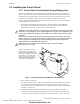
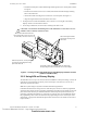
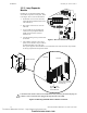
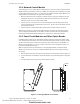
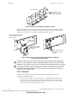
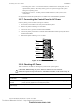
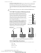
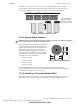
Table Of Contents
- Table of Contents
- Section 1 About This Manual
- Section 2 System Overview
- Section 3 Installation
- 3.1 Preparing for Installation
- 3.2 Installation Checklist
- 3.3 Mounting a Cabinet
- 3.4 Laying Out Equipment in Cabinet and Chassis
- 3.5 Installing the Control Panel
- 3.5.1 Control Panel Circuit Board & Keypad/Display Unit
- 3.5.2 Using NCA as Primary Display
- 3.5.3 Loop Expander Module
- 3.5.4 Network Control Module
- 3.5.5 Panel Circuit Modules and Other Option Boards
- 3.5.6 Overview
- 3.5.7 Connecting the Control Panel to AC Power
- 3.5.8 Checking AC Power
- 3.5.9 Installing and Connecting the Batteries
- 3.5.10 APS-6R Auxiliary Power Supply Connections
- 3.5.11 External DC Power Output Connections
- 3.5.12 NAC Connections & Releasing Circuits
- 3.5.13 Output Relay Connections
- 3.5.14 Backup-Alarm Switches
- 3.5.15 Installing a Transmitter Module TM-4
- 3.6 UL Power-limited Wiring Requirements
- 3.7 Installing Panel Circuit Modules
- 3.8 Auxiliary Relay Module (ARM-4): Product-Specific Details
- 3.9 Installing Remote Printers and/or CRT
- 3.10 Wiring a Signaling Line Circuit (SLC)
- Section 4 Applications
- Section 5 Testing the System
- Appendix A Power Supply Calculations
- Appendix B Electrical Specifications
- Appendix C Compatible Equipment
- Appendix D Canadian Applications
- Index

Installation Installing the Control Panel
40 NFS-640 Installation Manual P/N 51332:B2 07/27/2004
The Supervisory and Security contacts can also be configured as Alarm contacts by setting
switches SW1 and SW5 away from the factory default positions shown in Figure 18. Follow
sequence of steps in Section 3.2 “Installation Checklist”, Table 2; this is part of Step 6.
Figure 18 Form-C Relay Connections
3.5.14 Backup-Alarm Switches
Backup alarm switches are provided that enable NACs
and the alarm relay to activate during a backup alarm
condition. If the main board’s microcontroller fails and
an alarm is reported by any detector or a monitor
module that has backup reporting enabled, the NAC
will turn on if the corresponding switch was enabled.
The alarm will activate during microcontroller failure
regardless of the settings of Switch 6-9.
• Switch 6 - NAC#1
• Switch 7 - NAC#2
• Switch 8 - NAC#3
• Switch 9 - NAC#4
So, for example, if Switch 6 and Switch 8 were enabled at the time of an alarm during
microcontroller failure, NAC#1 and NAC#3 would activate. Follow sequence of steps in Section
3.2 “Installation Checklist”, Table 2; this is Step 7.
3.5.15 Installing a Transmitter Module TM-4
TM-4 is power-limited. Connections are on TB7 nonresettable output and TB13 EIA-485 ACS
Mode. Refer to the Transmitter Module TM-4 installation document for installation details.
ALARM RELAY
NO NC C
TROUBLE RELAY
NO NC C
SUPERVISORY RELAY
NO NC C
SECURITY RELAY
NO NC C
TB8
TB9 TB10
TB11
SW1
SW5
SUPV ALARM SECUR ALARM
SW1 set to Supervisory
SW5 set to Security
Move switch to opposite
position to set to Alarm.
nfs640-relay.cdr
!
WARNING: Do not enable the BACKUP option switch for any of the four Notification Appliance
Circuits (NACs) if they are used for releasing functions!
Figure 19 Backup Alarm Switches
SW6
NAC
SW7
ENAB
DISAB
SW8
SW9
13
24
nfs640-sw6-9.cdr
Technical Manuals Online! - http://www.tech-man.com
firealarmresources.com