
Instruction Manual
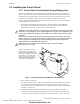
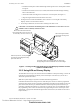
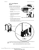
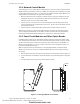
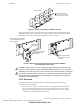
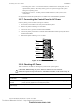
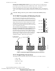
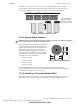
Table Of Contents
- Table of Contents
- Section 1 About This Manual
- Section 2 System Overview
- Section 3 Installation
- 3.1 Preparing for Installation
- 3.2 Installation Checklist
- 3.3 Mounting a Cabinet
- 3.4 Laying Out Equipment in Cabinet and Chassis
- 3.5 Installing the Control Panel
- 3.5.1 Control Panel Circuit Board & Keypad/Display Unit
- 3.5.2 Using NCA as Primary Display
- 3.5.3 Loop Expander Module
- 3.5.4 Network Control Module
- 3.5.5 Panel Circuit Modules and Other Option Boards
- 3.5.6 Overview
- 3.5.7 Connecting the Control Panel to AC Power
- 3.5.8 Checking AC Power
- 3.5.9 Installing and Connecting the Batteries
- 3.5.10 APS-6R Auxiliary Power Supply Connections
- 3.5.11 External DC Power Output Connections
- 3.5.12 NAC Connections & Releasing Circuits
- 3.5.13 Output Relay Connections
- 3.5.14 Backup-Alarm Switches
- 3.5.15 Installing a Transmitter Module TM-4
- 3.6 UL Power-limited Wiring Requirements
- 3.7 Installing Panel Circuit Modules
- 3.8 Auxiliary Relay Module (ARM-4): Product-Specific Details
- 3.9 Installing Remote Printers and/or CRT
- 3.10 Wiring a Signaling Line Circuit (SLC)
- Section 4 Applications
- Section 5 Testing the System
- Appendix A Power Supply Calculations
- Appendix B Electrical Specifications
- Appendix C Compatible Equipment
- Appendix D Canadian Applications
- Index

Installing the Control Panel Installation
NFS-640 Installation Manual P/N 51332:B2 07/27/2004 39
24 VDC Non-resettable Power Circuit. The power supply provides one 24 VDC filtered,
power-limited, non-resettable power output, capable of up to 1.25 A. Use this circuit to power
devices that require low-noise 24 VDC power (such as annunciators or the TM-4).
Connect external field wires to power supply terminals TB7 NONRST(+)and(–) to provide up to
1.25 A of non-resettable current for powering external devices such as annunciators. See Figure 15
above.
3.5.12 NAC Connections & Releasing Circuits
The control panel provides four NAC terminals as shown in
Figure 16. Each can be configured as Style Y (Class B) or Style
Z (Class A) as shown in Figure 17. Each circuit can provide 2.5
A of current, but the total current drawn from the main power
supply cannot exceed 6.0 A in alarm condition (refer to Table
12). NAC circuits are supervised and power-limited. Use UL-
listed 24 VDC notification appliances only (refer to the Notifier
Device Compatibility Document).
Note: Any NAC can be programmed as a releasing circuit,
but only one releasing device per circuit is allowed. For more
information, refer to Section 4.5 “Releasing Applications” in
this manual and the NFS-640 Programming Manual. Refer to
the Device Compatibility Document, for UL-listed compatible
releasing devices. Sample connections for NAC terminals are
shown in Figure 17. Follow sequence of steps in Section 3.2
“Installation Checklist”, Table 2; this is part of Step 6.
Figure 17 Notification Appliance/Releasing Circuit Connections
3.5.13 Output Relay Connections
The panel provides a set of Form-C relays. These are rated for 2.0 A at 30 VDC (resistive):
• Alarm - TB8
• Trouble - TB9
• Supervisory - TB10
• Security - TB11
!
CAUTION: During system reset, power remains at terminals TB7 NONRST(+)and(–).
B+ B- A+ A- B+ B- A+ A- B+ B- A+ A- B+ B- A+ A-
Figure 16 NAC Terminals
TB6 - NAC#1
TB5 - NAC#2
TB4 - NAC#3
TB3 - NAC#4
nfs640-NACS.cdr
B+ B– A+ A– B+ B– A+ A– B+ B– A+ A–
nfs640-nacout.cdr
Style Y (Class B)
Connection
Style Z (Class A)
Connection
Unused
Circuits
UL-listed ELR-2.2K,
1/2 W (supplied)
Technical Manuals Online! - http://www.tech-man.com
firealarmresources.com