
Instruction Manual
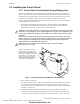
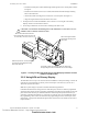
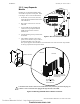
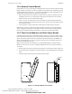
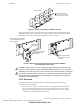
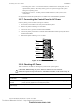
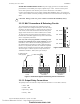
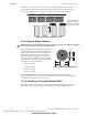
Table Of Contents
- Table of Contents
- Section 1 About This Manual
- Section 2 System Overview
- Section 3 Installation
- 3.1 Preparing for Installation
- 3.2 Installation Checklist
- 3.3 Mounting a Cabinet
- 3.4 Laying Out Equipment in Cabinet and Chassis
- 3.5 Installing the Control Panel
- 3.5.1 Control Panel Circuit Board & Keypad/Display Unit
- 3.5.2 Using NCA as Primary Display
- 3.5.3 Loop Expander Module
- 3.5.4 Network Control Module
- 3.5.5 Panel Circuit Modules and Other Option Boards
- 3.5.6 Overview
- 3.5.7 Connecting the Control Panel to AC Power
- 3.5.8 Checking AC Power
- 3.5.9 Installing and Connecting the Batteries
- 3.5.10 APS-6R Auxiliary Power Supply Connections
- 3.5.11 External DC Power Output Connections
- 3.5.12 NAC Connections & Releasing Circuits
- 3.5.13 Output Relay Connections
- 3.5.14 Backup-Alarm Switches
- 3.5.15 Installing a Transmitter Module TM-4
- 3.6 UL Power-limited Wiring Requirements
- 3.7 Installing Panel Circuit Modules
- 3.8 Auxiliary Relay Module (ARM-4): Product-Specific Details
- 3.9 Installing Remote Printers and/or CRT
- 3.10 Wiring a Signaling Line Circuit (SLC)
- Section 4 Applications
- Section 5 Testing the System
- Appendix A Power Supply Calculations
- Appendix B Electrical Specifications
- Appendix C Compatible Equipment
- Appendix D Canadian Applications
- Index

Installation Installing the Control Panel
38 NFS-640 Installation Manual P/N 51332:B2 07/27/2004
3.5.9 Installing and Connecting the Batteries
Batteries (2) are installed in the control panel cabinet or in a separate battery cabinet which can be
mounted below the control panel or up to 20 feet (6.096 m) away from the control panel, in the
same room.
Connect the battery as follows (see Figure 14 above):
1. Install batteries (2) into bottom of cabinet or into separate battery cabinet.
2. Connect the red cable from TB1(+) on the control panel to the positive (+) terminal of one
battery.
3. Connect the black cable from TB1(–) on the control panel to the negative (–) terminal of the
other battery.
4. Connect the remaining cable between the negative (-) terminal on the first battery to the
positive (+) terminal on the second battery.
3.5.10 APS-6R Auxiliary Power Supply Connections
If an optional APS-6R power supply is installed in the cabinet, connect it with no power applied;
follow sequence of steps in Section 3.2 “Installation Checklist”, Table 2; this is Step 4. For all
information pertaining to these connections see the APS-6R Instruction Manual.
3.5.11 External DC Power Output Connections
Terminal TB7 provides two (2) power outputs, resettable and non-resettable. Each output is power-
limited. Follow sequence of steps in Section 3.2 “Installation Checklist”, Table 2; this is part of
Step 6.
Figure 15 Power Supply DC Outputs - TB7
24 VDC Resettable Power Circuit (Four-Wire Smoke Detectors). The power supply
provides a single 24 VDC filtered, power-limited, resettable power circuit for devices that require
resettable power (such as four-wire smoke detectors). This circuit is power-limited, but must be
supervised. To provide supervision, install a UL-listed end-of-line power supervision relay (such as
the A77-716B) after the last device. Connect the power supervision relay normally open contact in
series with an Initiating Device Circuit (IDC). The four-wire power circuit energizes the power
supervision relay. When you reset the system, the control panel removes power from these
terminals for approximately 15 seconds.
Connect external field wires to the power supply terminals TB7 RESET(+)and(–) to provide up to
1.25 A of current for powering four-wire smoke detectors. See Figure 15 above.
!
w
WARNING: Battery contains sulfuric acid which can cause severe burns to the skin and eyes, and
can destroy fabrics. If contact is made with sulfuric acid, immediately flush skin or eyes with
water for 15 minutes and seek immediate medical attention.
!
WARNING: Do not connect the Battery Interconnect Cables (P/N 75560 and 75561) at this time.
Make this connection AFTER initial system primary powerup. Follow sequence of steps in Section
3.2 “Installation Checklist”, Table 2; this is Step 17.
+ – + –
TB7
Non-resettable
Power
nfs640-dcout.cdr
Resettable
Power
Technical Manuals Online! - http://www.tech-man.com
firealarmresources.com