
Instruction Manual
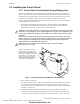
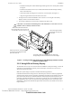
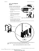
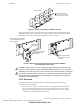
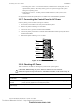
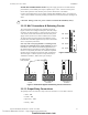
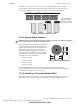
Table Of Contents
- Table of Contents
- Section 1 About This Manual
- Section 2 System Overview
- Section 3 Installation
- 3.1 Preparing for Installation
- 3.2 Installation Checklist
- 3.3 Mounting a Cabinet
- 3.4 Laying Out Equipment in Cabinet and Chassis
- 3.5 Installing the Control Panel
- 3.5.1 Control Panel Circuit Board & Keypad/Display Unit
- 3.5.2 Using NCA as Primary Display
- 3.5.3 Loop Expander Module
- 3.5.4 Network Control Module
- 3.5.5 Panel Circuit Modules and Other Option Boards
- 3.5.6 Overview
- 3.5.7 Connecting the Control Panel to AC Power
- 3.5.8 Checking AC Power
- 3.5.9 Installing and Connecting the Batteries
- 3.5.10 APS-6R Auxiliary Power Supply Connections
- 3.5.11 External DC Power Output Connections
- 3.5.12 NAC Connections & Releasing Circuits
- 3.5.13 Output Relay Connections
- 3.5.14 Backup-Alarm Switches
- 3.5.15 Installing a Transmitter Module TM-4
- 3.6 UL Power-limited Wiring Requirements
- 3.7 Installing Panel Circuit Modules
- 3.8 Auxiliary Relay Module (ARM-4): Product-Specific Details
- 3.9 Installing Remote Printers and/or CRT
- 3.10 Wiring a Signaling Line Circuit (SLC)
- Section 4 Applications
- Section 5 Testing the System
- Appendix A Power Supply Calculations
- Appendix B Electrical Specifications
- Appendix C Compatible Equipment
- Appendix D Canadian Applications
- Index

Installing the Control Panel Installation
NFS-640 Installation Manual P/N 51332:B2 07/27/2004 37
• Secondary power source – 24 VDC from batteries, installed in the control panel (or in an
optional battery cabinet). Secondary (battery) power is required to support the system
during loss of primary power.
• External power sources – 24 VDC power for Smoke Detectors (4 wire), NACs, and
Annunciators.
See Appendix B “Electrical Specifications” for details and overall installation guidelines.
3.5.7 Connecting the Control Panel to AC Power
Connect primary power as follows (see Figure 14 below):
1. Turn off the circuit breaker at the main power distribution panel.
2. Remove the plastic insulating cover from TB2.
3. Connect the service ground to terminal marked EARTH.
4. Connect the primary neutral line to terminal marked NEUTRAL and the primary Hot line to
terminal marked HOT.
5. Reinstall the plastic insulating cover over TB2.
Figure 14 AC & DC Power Connections
3.5.8 Checking AC Power
Table 4 contains a checklist for checking the system with AC power applied:
EARTH HOTNEUTRALBATT –BATT+
TB1
TB2
nfs640-acdc.cdr
Hot
Neutral
Ground
(Earth)
Battery (-)
Battery (+)
!
CAUTION: While checking AC power, make sure batteries are not connected.
Follow the sequence of steps in Section 3.2 “Installation Checklist”, Table 2; this is Step 16.
Component Status
Control panel
circuit board
The green AC Power indicator on; the system Trouble indicator on because batteries are not
connected.
Each panel circuit
module
The yellow Trouble indicator may come on for approximately 10 seconds after applying AC
power. (This only applies to an unconfigured system.)
Each auxiliary
power supply
The yellow Trouble indicator comes on because batteries are not connected.
Table 4 AC Power Checklist
Technical Manuals Online! - http://www.tech-man.com
firealarmresources.com