
Instruction Manual
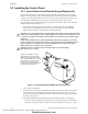
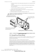
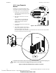
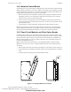
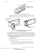
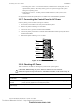
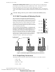
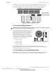
Table Of Contents
- Table of Contents
- Section 1 About This Manual
- Section 2 System Overview
- Section 3 Installation
- 3.1 Preparing for Installation
- 3.2 Installation Checklist
- 3.3 Mounting a Cabinet
- 3.4 Laying Out Equipment in Cabinet and Chassis
- 3.5 Installing the Control Panel
- 3.5.1 Control Panel Circuit Board & Keypad/Display Unit
- 3.5.2 Using NCA as Primary Display
- 3.5.3 Loop Expander Module
- 3.5.4 Network Control Module
- 3.5.5 Panel Circuit Modules and Other Option Boards
- 3.5.6 Overview
- 3.5.7 Connecting the Control Panel to AC Power
- 3.5.8 Checking AC Power
- 3.5.9 Installing and Connecting the Batteries
- 3.5.10 APS-6R Auxiliary Power Supply Connections
- 3.5.11 External DC Power Output Connections
- 3.5.12 NAC Connections & Releasing Circuits
- 3.5.13 Output Relay Connections
- 3.5.14 Backup-Alarm Switches
- 3.5.15 Installing a Transmitter Module TM-4
- 3.6 UL Power-limited Wiring Requirements
- 3.7 Installing Panel Circuit Modules
- 3.8 Auxiliary Relay Module (ARM-4): Product-Specific Details
- 3.9 Installing Remote Printers and/or CRT
- 3.10 Wiring a Signaling Line Circuit (SLC)
- Section 4 Applications
- Section 5 Testing the System
- Appendix A Power Supply Calculations
- Appendix B Electrical Specifications
- Appendix C Compatible Equipment
- Appendix D Canadian Applications
- Index

Installation Installing the Control Panel
36 NFS-640 Installation Manual P/N 51332:B2 07/27/2004
Figure 12 Location of Stand-offs on Module Chassis
Note: See the BMP-1 Product Installation Drawing for details if considering mounting the module
behind blank module plate in a dress plate or annunciator backbox. This dress plate is suitable for
modules that do not need to be visible or accessible when the door is closed.
Figure 13 Mounting Single-space Blank Plate with Optional Module
Connecting the Power Cables
3.5.6 Overview
Complete all mounting procedures and check all wiring before applying power. Electrical
connections include the following:
• Primary AC power source – 120 VAC, 50/60 Hz, 3.0 A (NFS-640E uses 240 VAC, 50/60
Hz, 1.5 A) from line voltage source. Overcurrent protection for this circuit must comply
with Article 760 of the National Electrical Code (NEC) and/or local codes. Use 12 AWG
(3.1 mm
2
) wire (maximum) with a 600-volt rating.
CHS-4studpos.cdr
Install stand-offs on these
two (2) studs in any one of
four positions along chassis.
Chassis CHS-4N
Single-space
blank plate
Fasten optional module to
the plate with four screws
(included).
tm4adp4.cdr
Mount optional module
onto standoffs on the
blank plate
Mount single-space blank plate
onto compatible dress panel or
backbox trim ring
!
WARNING: Remove all power sources to equipment while connecting electrical components.
Leave the external, main power breaker OFF until installation of the entire system is complete.
!
WARNING: Several sources of power can be connected to the control panel. Before servicing the
control panel, disconnect all sources of input power including the battery. While energized, the
control panel and associated equipment can be damaged by removing and/or inserting cards,
modules, or interconnecting cables.
Technical Manuals Online! - http://www.tech-man.com
firealarmresources.com