
Instruction Manual
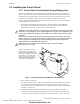
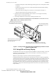
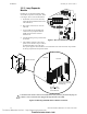
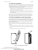
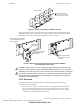
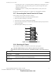
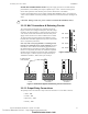
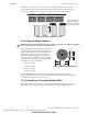
Table Of Contents
- Table of Contents
- Section 1 About This Manual
- Section 2 System Overview
- Section 3 Installation
- 3.1 Preparing for Installation
- 3.2 Installation Checklist
- 3.3 Mounting a Cabinet
- 3.4 Laying Out Equipment in Cabinet and Chassis
- 3.5 Installing the Control Panel
- 3.5.1 Control Panel Circuit Board & Keypad/Display Unit
- 3.5.2 Using NCA as Primary Display
- 3.5.3 Loop Expander Module
- 3.5.4 Network Control Module
- 3.5.5 Panel Circuit Modules and Other Option Boards
- 3.5.6 Overview
- 3.5.7 Connecting the Control Panel to AC Power
- 3.5.8 Checking AC Power
- 3.5.9 Installing and Connecting the Batteries
- 3.5.10 APS-6R Auxiliary Power Supply Connections
- 3.5.11 External DC Power Output Connections
- 3.5.12 NAC Connections & Releasing Circuits
- 3.5.13 Output Relay Connections
- 3.5.14 Backup-Alarm Switches
- 3.5.15 Installing a Transmitter Module TM-4
- 3.6 UL Power-limited Wiring Requirements
- 3.7 Installing Panel Circuit Modules
- 3.8 Auxiliary Relay Module (ARM-4): Product-Specific Details
- 3.9 Installing Remote Printers and/or CRT
- 3.10 Wiring a Signaling Line Circuit (SLC)
- Section 4 Applications
- Section 5 Testing the System
- Appendix A Power Supply Calculations
- Appendix B Electrical Specifications
- Appendix C Compatible Equipment
- Appendix D Canadian Applications
- Index

Installing the Control Panel Installation
NFS-640 Installation Manual P/N 51332:B2 07/27/2004 35
3.5.4 Network Control Module
If networking two or more control panels (including NCAs), each unit requires a Network Control
Module (NCM); wire and fiber versions are available. The NCM-W/F can be installed in any panel
circuit module position (see Section 3.5.5 “Panel Circuit Modules and Other Option Boards”); the
default position is immediately to the right of the control panel.
1. Mount the NCM in the selected position. If another board is going to be mounted in the slot
immediately in front of it, use stand-offs provided with the next board to secure it in place.
Otherwise use the screws provided with the NCM.
2. Connect J1 on the control panel to J3 on the NCM using the network cable provided (P/N
75556) as described in the NCM Installation Document. Do not connect two NCMs via NUP
ports (aka NUP to NUP).
3. Connect Channel A and/or Channel B as described in the NCM Installation Document.
Note: See the Noti•Fire•Net Manual and NCM Installation Document for wiring diagrams and
system configuration information. See the BMP-1 Product Installation Drawing if considering
mounting the module behind blank module plate in a dress plate or annunciator backbox.
3.5.5 Panel Circuit Modules and Other Option Boards
If installing option boards into a CAB-4 Series backbox, mount and connect those boards at this
time. General instructions follow; the sections about individual option boards contain any module-
specific instructions. Option boards can be mounted in the front (fourth) layer of CHS-M2 (see
flanges as shown in Figure 8), or in any position on the other row(s) of equipment, using 0.937"
(23.8 mm) standoffs between layers.
Note: An option board can be mounted above a Loop Expander Module or Network Control
Module; for ease of access, be sure to complete installation of those devices before mounting a
second layer.
1. Slide the tabs at the bottom of the option board into slots on the chassis as shown in Figure 11.
2. Lay the board back onto the flanges so that the studs line up with mounting holes on the option
board.
3. Attach the option board using screws provided with the module.
Figure 11 Inserting a Module into a Chassis
nfs640-mnticm.cdr
Shown with CHS-M2
Module
Screw
Slots
Shown with CHS-4N
Technical Manuals Online! - http://www.tech-man.com
firealarmresources.com