
Instruction Manual
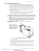
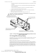
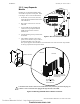
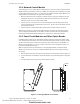
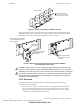
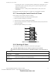
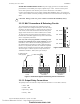
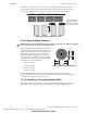
Table Of Contents
- Table of Contents
- Section 1 About This Manual
- Section 2 System Overview
- Section 3 Installation
- 3.1 Preparing for Installation
- 3.2 Installation Checklist
- 3.3 Mounting a Cabinet
- 3.4 Laying Out Equipment in Cabinet and Chassis
- 3.5 Installing the Control Panel
- 3.5.1 Control Panel Circuit Board & Keypad/Display Unit
- 3.5.2 Using NCA as Primary Display
- 3.5.3 Loop Expander Module
- 3.5.4 Network Control Module
- 3.5.5 Panel Circuit Modules and Other Option Boards
- 3.5.6 Overview
- 3.5.7 Connecting the Control Panel to AC Power
- 3.5.8 Checking AC Power
- 3.5.9 Installing and Connecting the Batteries
- 3.5.10 APS-6R Auxiliary Power Supply Connections
- 3.5.11 External DC Power Output Connections
- 3.5.12 NAC Connections & Releasing Circuits
- 3.5.13 Output Relay Connections
- 3.5.14 Backup-Alarm Switches
- 3.5.15 Installing a Transmitter Module TM-4
- 3.6 UL Power-limited Wiring Requirements
- 3.7 Installing Panel Circuit Modules
- 3.8 Auxiliary Relay Module (ARM-4): Product-Specific Details
- 3.9 Installing Remote Printers and/or CRT
- 3.10 Wiring a Signaling Line Circuit (SLC)
- Section 4 Applications
- Section 5 Testing the System
- Appendix A Power Supply Calculations
- Appendix B Electrical Specifications
- Appendix C Compatible Equipment
- Appendix D Canadian Applications
- Index

Installation Installing the Control Panel
34 NFS-640 Installation Manual P/N 51332:B2 07/27/2004
3.5.3 Loop Expander
Module
Installing a Loop Expander Module adds a
second SLC loop to the control panel. Refer
to the Figure 10 for connector illustrations.
1. Thread four (4) 0.937 inch (23.8 mm)
stand-offs through indicated holes in the
CPU-640 board.
2. Plug stacker-connector into J3 on the
CPU-640.
3. Lay the LEM onto the standoffs and
connect the Loop Expander Module
(LEM) into the stacker-connector
attached to J3.
4. Attach LEM using screws provided with
the module.
5. After LEM is mounted on the control
panel, connect the SLC loops to TB1 on
the LEM and TB16 on the CPU-640.
This system supports either FlashScan or CLIP mode devices. Refer to the SLC loop manual
for wiring requirements and specific details.
Figure 10 Mounting LEM-320 with the Stacker-connector
J1
B+
A
+B-
A
-
LEM-320PCA
TB1
B+ A+ B- A-
TB1
Lem-slc.cdr
Figure 9 SLC Connections for LEM-320
CPU-640
Stacker-connector
LEM-320
J1
J3
The long-pin end
plugs into the back
of the LEM board.
The short-pin end plugs
directly into the top of the
CPU-640 plug.
!
CAUTION: If the stacker-connector is installed incorrectly, the short-pin end of the plug can
to make a secure connection when plugged through the back of the LEM.
Technical Manuals Online! - http://www.tech-man.com
firealarmresources.com