
Instruction Manual
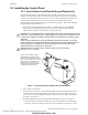
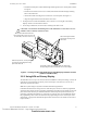
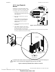
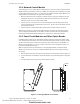
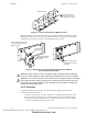
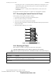
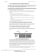
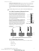
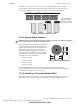
Table Of Contents
- Table of Contents
- Section 1 About This Manual
- Section 2 System Overview
- Section 3 Installation
- 3.1 Preparing for Installation
- 3.2 Installation Checklist
- 3.3 Mounting a Cabinet
- 3.4 Laying Out Equipment in Cabinet and Chassis
- 3.5 Installing the Control Panel
- 3.5.1 Control Panel Circuit Board & Keypad/Display Unit
- 3.5.2 Using NCA as Primary Display
- 3.5.3 Loop Expander Module
- 3.5.4 Network Control Module
- 3.5.5 Panel Circuit Modules and Other Option Boards
- 3.5.6 Overview
- 3.5.7 Connecting the Control Panel to AC Power
- 3.5.8 Checking AC Power
- 3.5.9 Installing and Connecting the Batteries
- 3.5.10 APS-6R Auxiliary Power Supply Connections
- 3.5.11 External DC Power Output Connections
- 3.5.12 NAC Connections & Releasing Circuits
- 3.5.13 Output Relay Connections
- 3.5.14 Backup-Alarm Switches
- 3.5.15 Installing a Transmitter Module TM-4
- 3.6 UL Power-limited Wiring Requirements
- 3.7 Installing Panel Circuit Modules
- 3.8 Auxiliary Relay Module (ARM-4): Product-Specific Details
- 3.9 Installing Remote Printers and/or CRT
- 3.10 Wiring a Signaling Line Circuit (SLC)
- Section 4 Applications
- Section 5 Testing the System
- Appendix A Power Supply Calculations
- Appendix B Electrical Specifications
- Appendix C Compatible Equipment
- Appendix D Canadian Applications
- Index

Installing the Control Panel Installation
NFS-640 Installation Manual P/N 51332:B2 07/27/2004 33
• Thread the stacked pairs of stand-offs through mounting holes on the control panel as shown
in Figure 8.
• Thread two P/N 42166 (0.937 inch, 23.8 mm) male-female stand-offs through mounting
holes in the chassis rail.
• Attach ribbon cable from keypad to J4 connector on control panel. (See Figure 3.)
• Align the keypad with the stand-offs and screw it down.
5. If using the NCA instead of the KDM-2, refer to Section 3.5.2 “Using NCA as Primary
Display” and the NCA Installation Manual.
6. If not using an LEM-320, secure the last 4 mounting holes with screws.
Figure 8 Locating and Aligning Stand-offs for Keypad/Display and Panel Circuits
(Chassis CHS-M2 shown)
3.5.2 Using NCA as Primary Display
The NFS-640 can be set up to use an NCA instead of a KDM-2. In this system design, connect the
network port on the NFS-640 (J1) directly to the network port on the NCA (J3); see the NCA
Manual for specific instructions.
Note: This system design is required in Canadian stand-alone applications.
If the NFS-640 and NCA are being used as a stand-alone pair, each device must be programmed
separately using VeriFire Tools in its off-line programming mode. Because the VeriFire Tools com-
puter also uses the network port, NFS-640 and NCA must be temporarily disconnected for pro-
gramming. If the NFS-640 with NCA is connected to a network, there are two additional options
for programming: either connect the VeriFire Tools programming PC to the network port on the
NCM board, or program the NFS-640 through another network node. (See VeriFire Tools on-line
help for details.)
!
CAUTION: It is critical that all mounting holes of the NFS-640 are secured with a screw or
standoff to insure continuity of Earth Ground.
Stack of two male-female stand-offs:
connect P/N 42185 (2.0 inch, 50.8 mm)
to P/N 42186 (1.312 inch, 33.33 mm).
Note: If not using this location,
secure these mounting holes
with screws.
Attach two (0.937 inch, 23.8 mm) stand-offs
to chassis rail; screw keypad mounting
plate to the stand-offs.
Lower edge of panel circuit modules slide into chassis slots,
and upper edge mounts onto PEM studs on the chassis flange.
CHS-M2-0604-assy.wmf
Technical Manuals Online! - http://www.tech-man.com
firealarmresources.com