
Instruction Manual
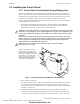
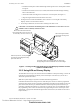
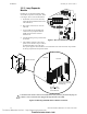
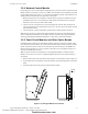
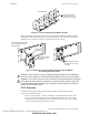
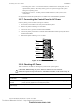
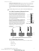
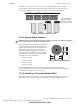
Table Of Contents
- Table of Contents
- Section 1 About This Manual
- Section 2 System Overview
- Section 3 Installation
- 3.1 Preparing for Installation
- 3.2 Installation Checklist
- 3.3 Mounting a Cabinet
- 3.4 Laying Out Equipment in Cabinet and Chassis
- 3.5 Installing the Control Panel
- 3.5.1 Control Panel Circuit Board & Keypad/Display Unit
- 3.5.2 Using NCA as Primary Display
- 3.5.3 Loop Expander Module
- 3.5.4 Network Control Module
- 3.5.5 Panel Circuit Modules and Other Option Boards
- 3.5.6 Overview
- 3.5.7 Connecting the Control Panel to AC Power
- 3.5.8 Checking AC Power
- 3.5.9 Installing and Connecting the Batteries
- 3.5.10 APS-6R Auxiliary Power Supply Connections
- 3.5.11 External DC Power Output Connections
- 3.5.12 NAC Connections & Releasing Circuits
- 3.5.13 Output Relay Connections
- 3.5.14 Backup-Alarm Switches
- 3.5.15 Installing a Transmitter Module TM-4
- 3.6 UL Power-limited Wiring Requirements
- 3.7 Installing Panel Circuit Modules
- 3.8 Auxiliary Relay Module (ARM-4): Product-Specific Details
- 3.9 Installing Remote Printers and/or CRT
- 3.10 Wiring a Signaling Line Circuit (SLC)
- Section 4 Applications
- Section 5 Testing the System
- Appendix A Power Supply Calculations
- Appendix B Electrical Specifications
- Appendix C Compatible Equipment
- Appendix D Canadian Applications
- Index

Installation Installing the Control Panel
32 NFS-640 Installation Manual P/N 51332:B2 07/27/2004
3.5 Installing the Control Panel
3.5.1 Control Panel Circuit Board & Keypad/Display Unit
The control panel mounts in chassis CHS-M2, which is usually positioned in the top row of the
backbox. The control panel’s CPU occupies three positions at the back of the chassis; the KDM-2
occupies two positions flush with the door. The NCA may be door-mounted directly in front of the
control panel if no KDM-2 is being used; see the NCA Manual for details and restrictions.
Note: For initial release of NFS-640, mounting instructions were different. Refer to the installation
manual shipped with the panel (Rev A).
1. Verify height of the mounting stud in the backbox. In older backboxes, the stud must be
shortened to prevent damage to the CPU-640. All electronics must be removed from the
backbox before shortening. See instructions in the warning below.
Figure 7 Using the Redesigned CHS-M2 with Older Backboxes
2. Screw chassis to the backbox.
3. Attach CPU-640 to the chassis. Slide control-panel tabs into slots on chassis and lay the board
onto stand-offs so that mounting holes line up with those on the chassis. Secure with six (6)
screws (four across the top of the board, and two to the left of the power supply) provided with
the chassis. (See Figure 8.)
4. If installing KDM-2, install the stand-offs included with the keyboard kit. (See Figure 8.)
• The upper edge of the keyboard mounting plate rests on two stacked pairs of male-female
stand-offs. Connect P/N 42185 (2.0 inch, 50.8 mm) to P/N 42186 (1.312 inch, 33.33 mm).
!
WARNING: For retrofit applications, verify the height of the backbox’s mounting stud on left side
under CPU, as shown in Figure 7 below. Stud height must not exceed 0.375 in. (9.525 mm). Early
versions of the CAB-4 Series backboxes and all CAB-3 Series backboxes have studs that require
shortening.
Failure to shorten this 0.625 in. (15.875 mm) mounting stud will cause damage to the control
panel’s CPU. Remove electronics from backbox, permanently mount empty CHS-M2 chassis to
backbox, apply nut to mounting stud to protect threading, then cut stud to proper length.
Reinstall electronics as discussed in the steps below.
!
WARNING: Do not cut without washers and nuts in place to protect threading.
Wear protective eye covering.
If using a new CHS-M2 in a CAB-3
series backbox or in a CAB-4 series
backbox manufactured before October
2002, verify stud height and cut any stud
that exceeds 0.375 in. (9.525 mm) as
per Step 1 above if a CPU is being
mounted above it. Reinstall electronics
as discussed in the steps below.
CHS-M2-11-03-CAB-3.wmf
Technical Manuals Online! - http://www.tech-man.com
firealarmresources.com