
Instruction Manual
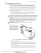
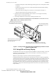
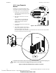
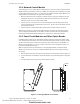
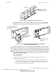
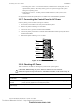
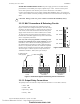
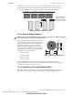
Table Of Contents
- Table of Contents
- Section 1 About This Manual
- Section 2 System Overview
- Section 3 Installation
- 3.1 Preparing for Installation
- 3.2 Installation Checklist
- 3.3 Mounting a Cabinet
- 3.4 Laying Out Equipment in Cabinet and Chassis
- 3.5 Installing the Control Panel
- 3.5.1 Control Panel Circuit Board & Keypad/Display Unit
- 3.5.2 Using NCA as Primary Display
- 3.5.3 Loop Expander Module
- 3.5.4 Network Control Module
- 3.5.5 Panel Circuit Modules and Other Option Boards
- 3.5.6 Overview
- 3.5.7 Connecting the Control Panel to AC Power
- 3.5.8 Checking AC Power
- 3.5.9 Installing and Connecting the Batteries
- 3.5.10 APS-6R Auxiliary Power Supply Connections
- 3.5.11 External DC Power Output Connections
- 3.5.12 NAC Connections & Releasing Circuits
- 3.5.13 Output Relay Connections
- 3.5.14 Backup-Alarm Switches
- 3.5.15 Installing a Transmitter Module TM-4
- 3.6 UL Power-limited Wiring Requirements
- 3.7 Installing Panel Circuit Modules
- 3.8 Auxiliary Relay Module (ARM-4): Product-Specific Details
- 3.9 Installing Remote Printers and/or CRT
- 3.10 Wiring a Signaling Line Circuit (SLC)
- Section 4 Applications
- Section 5 Testing the System
- Appendix A Power Supply Calculations
- Appendix B Electrical Specifications
- Appendix C Compatible Equipment
- Appendix D Canadian Applications
- Index

Laying Out Equipment in Cabinet and Chassis Installation
NFS-640 Installation Manual P/N 51332:B2 07/27/2004 31
Note: The initial release of chassis CHS-M2 used L-brackets and stand-offs of different lengths
than the current model; refer to Doc. 51332, Rev A.
From… To… Required Stand-off or Hardware
Chassis CHS-M2 Control panel or
module on first layer
Not applicable; integral to the chassis.
Control panel or
Option board, 1st layer
Option board, 2nd layer
(includes LEM-320)
4 male-female stand-offs of length 0.937 inch (23.8 mm)
P/N 42166.
Option board, 2nd layer Option board, 3rd layer 4 male-female stand-offs of length 0.937 inch (23.8 mm)
P/N 42166.
Chassis Option board, 4th layer
(flush with door)
Attaches directly to flanges on chassis. (Screws
provided with option boards & panel circuit modules)
Chassis Panel circuit module
(flush with door)
Attaches directly to flanges on chassis. (Screws
provided with option boards & panel circuit modules)
Control panel KDM-2 (upper edge) 2 stacks of male-female stand-offs:
•P/N 42185 (2.0 inch, 50.8 mm) and
•P/N 42186 (1.312 inch, 33.33 mm)
Chassis rail KDM-2 (lower edge) 2 male-female stand-offs of length 0.937 inch (23.8 mm)
P/N 42166.
Dress panel
DP-DISP or ADP-4B
NCA Attaches directly to dress panel.
(Nuts provided with NCA.)
Dress panel
DP-DISP or ADP-4B
Option board BMP-1 attaches to dress panel; option module attaches
to BMP-1 (screws provided with option module).
Table 3 Stand-off Lengths
Technical Manuals Online! - http://www.tech-man.com
firealarmresources.com