
Instruction Manual
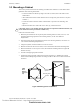
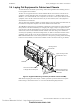
Table Of Contents
- Table of Contents
- Section 1 About This Manual
- Section 2 System Overview
- Section 3 Installation
- 3.1 Preparing for Installation
- 3.2 Installation Checklist
- 3.3 Mounting a Cabinet
- 3.4 Laying Out Equipment in Cabinet and Chassis
- 3.5 Installing the Control Panel
- 3.5.1 Control Panel Circuit Board & Keypad/Display Unit
- 3.5.2 Using NCA as Primary Display
- 3.5.3 Loop Expander Module
- 3.5.4 Network Control Module
- 3.5.5 Panel Circuit Modules and Other Option Boards
- 3.5.6 Overview
- 3.5.7 Connecting the Control Panel to AC Power
- 3.5.8 Checking AC Power
- 3.5.9 Installing and Connecting the Batteries
- 3.5.10 APS-6R Auxiliary Power Supply Connections
- 3.5.11 External DC Power Output Connections
- 3.5.12 NAC Connections & Releasing Circuits
- 3.5.13 Output Relay Connections
- 3.5.14 Backup-Alarm Switches
- 3.5.15 Installing a Transmitter Module TM-4
- 3.6 UL Power-limited Wiring Requirements
- 3.7 Installing Panel Circuit Modules
- 3.8 Auxiliary Relay Module (ARM-4): Product-Specific Details
- 3.9 Installing Remote Printers and/or CRT
- 3.10 Wiring a Signaling Line Circuit (SLC)
- Section 4 Applications
- Section 5 Testing the System
- Appendix A Power Supply Calculations
- Appendix B Electrical Specifications
- Appendix C Compatible Equipment
- Appendix D Canadian Applications
- Index
System Overview Voice Alarm System
26 NFS-640 Installation Manual P/N 51332:B2 07/27/2004
Audio Coupling Transformer ACT-1. Couples low-level audio to audio amplifiers or other
audio inputs, such as the AMG-1 Audio Message Generator. Provides Common Mode Noise
Rejection (CMNR), greatly reducing crosstalk from the SLCs. For more information and
installation instructions refer to the Voice Alarm System manual.
Audio Coupling Transformer ACT-2. When used with an AMG-1/-E, RM-1 and AA-30 this
unit provides a means to drive thousands of amplifiers in large audio system applications. The
ACT-2 provides electrical isolation between its input & output and attenuates the signal from high-
level audio to low-level audio. For more information and installation instructions refer to the ACT-2
Product Installation Drawing.
Additional Devices
The following devices are not part of the Voice Control System, but are listed here for continuity.
Remote Microphone (RM-1 and RM-1SA). Provides paging capabilities to speaker systems
driven by the low level audio source of the AMG-1. The RM-1 assembly can be installed in a
CAB-4 Series backbox, while the RM-1SA is installed in a CAB-RM cabinet. For more
information and installation instructions see the RM-1 Series Remote Microphone installation
document.
Quad Intelligent Audio Transponder - XPIQ. See product description on Page 20.
Technical Manuals Online! - http://www.tech-man.com
firealarmresources.com