
Instruction Manual
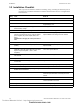
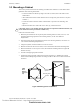
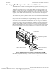
Table Of Contents
- Table of Contents
- Section 1 About This Manual
- Section 2 System Overview
- Section 3 Installation
- 3.1 Preparing for Installation
- 3.2 Installation Checklist
- 3.3 Mounting a Cabinet
- 3.4 Laying Out Equipment in Cabinet and Chassis
- 3.5 Installing the Control Panel
- 3.5.1 Control Panel Circuit Board & Keypad/Display Unit
- 3.5.2 Using NCA as Primary Display
- 3.5.3 Loop Expander Module
- 3.5.4 Network Control Module
- 3.5.5 Panel Circuit Modules and Other Option Boards
- 3.5.6 Overview
- 3.5.7 Connecting the Control Panel to AC Power
- 3.5.8 Checking AC Power
- 3.5.9 Installing and Connecting the Batteries
- 3.5.10 APS-6R Auxiliary Power Supply Connections
- 3.5.11 External DC Power Output Connections
- 3.5.12 NAC Connections & Releasing Circuits
- 3.5.13 Output Relay Connections
- 3.5.14 Backup-Alarm Switches
- 3.5.15 Installing a Transmitter Module TM-4
- 3.6 UL Power-limited Wiring Requirements
- 3.7 Installing Panel Circuit Modules
- 3.8 Auxiliary Relay Module (ARM-4): Product-Specific Details
- 3.9 Installing Remote Printers and/or CRT
- 3.10 Wiring a Signaling Line Circuit (SLC)
- Section 4 Applications
- Section 5 Testing the System
- Appendix A Power Supply Calculations
- Appendix B Electrical Specifications
- Appendix C Compatible Equipment
- Appendix D Canadian Applications
- Index
Peripheral Displays and Printers System Overview
NFS-640 Installation Manual P/N 51332:B2 07/27/2004 23
Annunciator Fixed Module - AFM-32A. Contains 32 red alarm LEDs, a system trouble LED,
an ON LINE/POWER LED, and a local panel sounder with a silence/acknowledge switch. The
AFM-32A is fixed at address 1, and will not accept expander modules.
2.9 Peripheral Displays and Printers
The control panel is compatible with the following printers and display devices:
•PRN-5 Printer
• Keltron Remote Printer VS4095
• CRT-2 Display Terminal
All EIA-232 devices must be located in the same room within 50 feet (15.24 m) of the control
panel.
Printer - PRN-5. The PRN-5 is an optional printer that connects directly to the control panel
through an EIA-232 interface (TB14) and can be located up to 50 feet (15.24 m) from the control
panel. It creates a printed record (80 columns of data on standard 9" x 11" tractor-feed paper) of all
system events (alarm, trouble) and status changes within the system. The printout is time-stamped
with the current time-of-day and date.
Keltron Remote Printer. The VS4095 is a two-color (red/black), 40-column, 24 VDC printer
that can print 50 messages in 90 seconds. This printer connects to the control panel through an EIA-
232 interface (TB14) and mounts in a separate cabinet next to the control panel. The VS4095 meets
UL fire and security requirements for an ancillary device.
For more information, contact the manufacturer (Keltron Corp., Waltham, MA)
Display Terminal - CRT-2. This optional display terminal connects to the control panel through
an EIA-232 interface (TB15). The terminal can control and view events, points and history reports,
control the system (Acknowledge, Alarm Silence, and System Reset). The terminal displays 26
lines by 80 columns and can be located up to 50 feet (15.24 m) from the control panel within the
same room.
Note: The CRT cannot be connected at the same time as the network.
2.10 Panel Circuit Modules
Introduction
The control panel supports the following modules to control external circuits and relays:
• Indicating Circuit Module (ICM-4RK) & Indicating Circuit Expander (ICE-4)
• Control Relay Module (CRM-4RK) & Control Relay Expander (CRE-4)
• Auxiliary Relay Module (ARM-4)
• Voice Control Module (VCM-4RK), Dual Channel Module (DCM-4RK) & Voice Control
Expander (VCE-4)
Up to eight of these modules (in any combination) can be controlled by the panel. Below are brief
descriptions of the modules; for a description of VCM-4RK and DCM-4RK, see Section 2.11
“Voice Alarm System”.
Indicating Circuit Module - ICM-4RK
Provides four (4) NACs for Style Y (Class B) or Style Z (Class A) operation. Circuits are field-
programmable to respond to a single initiating zone, a group of zones, or all initiating zones.
Maximum signaling current is 3 A per circuit or 6 A per module, limited by the power supply.
An Auxiliary Power Harness (P/N 71091) is provided. Note: ICM-4RK is not listed for use with
NFS-640 in releasing applications.
Technical Manuals Online! - http://www.tech-man.com
firealarmresources.com