
Instruction Manual
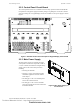
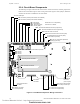
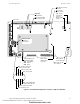
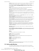
Table Of Contents
- Table of Contents
- Section 1 About This Manual
- Section 2 System Overview
- Section 3 Installation
- 3.1 Preparing for Installation
- 3.2 Installation Checklist
- 3.3 Mounting a Cabinet
- 3.4 Laying Out Equipment in Cabinet and Chassis
- 3.5 Installing the Control Panel
- 3.5.1 Control Panel Circuit Board & Keypad/Display Unit
- 3.5.2 Using NCA as Primary Display
- 3.5.3 Loop Expander Module
- 3.5.4 Network Control Module
- 3.5.5 Panel Circuit Modules and Other Option Boards
- 3.5.6 Overview
- 3.5.7 Connecting the Control Panel to AC Power
- 3.5.8 Checking AC Power
- 3.5.9 Installing and Connecting the Batteries
- 3.5.10 APS-6R Auxiliary Power Supply Connections
- 3.5.11 External DC Power Output Connections
- 3.5.12 NAC Connections & Releasing Circuits
- 3.5.13 Output Relay Connections
- 3.5.14 Backup-Alarm Switches
- 3.5.15 Installing a Transmitter Module TM-4
- 3.6 UL Power-limited Wiring Requirements
- 3.7 Installing Panel Circuit Modules
- 3.8 Auxiliary Relay Module (ARM-4): Product-Specific Details
- 3.9 Installing Remote Printers and/or CRT
- 3.10 Wiring a Signaling Line Circuit (SLC)
- Section 4 Applications
- Section 5 Testing the System
- Appendix A Power Supply Calculations
- Appendix B Electrical Specifications
- Appendix C Compatible Equipment
- Appendix D Canadian Applications
- Index

System Components System Overview
NFS-640 Installation Manual P/N 51332:B2 07/27/2004 15
Figure 4 Circuit Board Components: Jumpers, LEDs and Switches
NO NO NO NONC NC NC NCCCCC
+- +- + -+ -+ -
TX RX REF TX RX REF B+ A+ B- A-
EARTH NTRL HOTBATT+BATT- B+B- A+A- B+B- A+A- B+B- A+A- B+B- A+A-
JP6 - Ground
Fault Jumper
(SLC #1)
D67 -LEM-320
Ground Fault LED
D55 - Main SLC Ground
Fault LED
JP7 - Charger
Disable Jumper
SW1, SW5 -
Relay Switches
NAC LEDs
System Switches - ‘No
Keyboard Operation’
SW2 - Acknowledge
SW3 - Silence
SW4 - Reset
Disable - Enable
Switches for
Backup Alarm
nfs640-board2.cdr
D72 - General
Board Ground
Fault LED
JP12 - 200MA
Jumper
JP13 - General Board
Ground Fault Jumper
D82 - Power-on LED
(AC or battery)
D54 - ‘AC ON’ / Power LED
D76 - Pre-Alarm LED
D77 - Security LED
D81 - Point Disabled LED
D78 - Supervisory LED
D80 - Signals Silenced LED
D79 - System Trouble LED
D75 - Fire Alarm LED
Technical Manuals Online! - http://www.tech-man.com
firealarmresources.com