
Instruction Manual
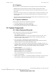
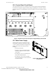
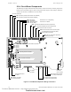
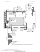
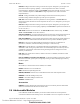
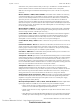
Table Of Contents
- Table of Contents
- Section 1 About This Manual
- Section 2 System Overview
- Section 3 Installation
- 3.1 Preparing for Installation
- 3.2 Installation Checklist
- 3.3 Mounting a Cabinet
- 3.4 Laying Out Equipment in Cabinet and Chassis
- 3.5 Installing the Control Panel
- 3.5.1 Control Panel Circuit Board & Keypad/Display Unit
- 3.5.2 Using NCA as Primary Display
- 3.5.3 Loop Expander Module
- 3.5.4 Network Control Module
- 3.5.5 Panel Circuit Modules and Other Option Boards
- 3.5.6 Overview
- 3.5.7 Connecting the Control Panel to AC Power
- 3.5.8 Checking AC Power
- 3.5.9 Installing and Connecting the Batteries
- 3.5.10 APS-6R Auxiliary Power Supply Connections
- 3.5.11 External DC Power Output Connections
- 3.5.12 NAC Connections & Releasing Circuits
- 3.5.13 Output Relay Connections
- 3.5.14 Backup-Alarm Switches
- 3.5.15 Installing a Transmitter Module TM-4
- 3.6 UL Power-limited Wiring Requirements
- 3.7 Installing Panel Circuit Modules
- 3.8 Auxiliary Relay Module (ARM-4): Product-Specific Details
- 3.9 Installing Remote Printers and/or CRT
- 3.10 Wiring a Signaling Line Circuit (SLC)
- Section 4 Applications
- Section 5 Testing the System
- Appendix A Power Supply Calculations
- Appendix B Electrical Specifications
- Appendix C Compatible Equipment
- Appendix D Canadian Applications
- Index

System Overview System Components
14 NFS-640 Installation Manual P/N 51332:B2 07/27/2004
2.2.4 Circuit Board Components
The following two figures illustrate the location of the various connections, switches, jumpers and
LEDs on the circuit board. Figure 3 shows wiring connections. Figure 4 shows jumpers, LEDs and
switches. See Section 3 “Installation” for more details.
Figure 3 Circuit Board Components: Wiring Connections
NO NO NO NONC NC NC NCCCCC
+- +- + -+ -+ -
TX RX REF TX RX REF B+ A+ B- A-
EARTH NTRL HOTBATT+BATT- B+B- A+A- B+B- A+A- B+B-A+A- B+B- A+A-
J3 - LEM-320
Connector
(SLC Loop #2)
J5 - Panel Circuits (supervised)
J6 - Panel Circuits (supervised)
J10 - Security Tamper Switch
J11 - Auxiliary Trouble Input
J4 - KDM-2
Connection
TB1 - Battery Connection
(over-current protected)
TB6 - NAC#1
TB5 - NAC#2
TB4 - NAC#3
TB3 - NAC#4
10 Amp Slo-Blow Fuse
P/N 12067
J7 - Accessory Power Connection
TB2 - AC Power Connection
nfs640-board2.cdr
All NAC Circuits: power-limited, supervised
TB16 - SLC #1 Connections (Detectors,
Modules) (supervised)
TB15 - EIA-232 PC/Terminal Connection (CRT)
J1 - Network/Service Connection (NUP)
(power-limited, supervised)
TB14 - EIA-232 Printer Connection
TB12 - EIA-485 Terminal Mode Connection (supervised)
TB13 - EIA-485 ACS Mode Connection (supervised)
TB7 - DC Power (24 VDC power-limited, non-resettable)
TB7 - DC Power (24 VDC power-limited, resettable)
J8 - Zone Code Input
TB8 - Alarm Relay
TB9 - Trouble Relay
TB10 - Supervisory Relay
TB11 - Security Relay
See Section 3.5.13 “Output Relay
Connections” for details.
Technical Manuals Online! - http://www.tech-man.com
firealarmresources.com