
Instruction Manual
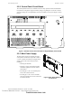
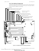
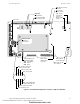
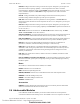
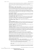
Table Of Contents
- Table of Contents
- Section 1 About This Manual
- Section 2 System Overview
- Section 3 Installation
- 3.1 Preparing for Installation
- 3.2 Installation Checklist
- 3.3 Mounting a Cabinet
- 3.4 Laying Out Equipment in Cabinet and Chassis
- 3.5 Installing the Control Panel
- 3.5.1 Control Panel Circuit Board & Keypad/Display Unit
- 3.5.2 Using NCA as Primary Display
- 3.5.3 Loop Expander Module
- 3.5.4 Network Control Module
- 3.5.5 Panel Circuit Modules and Other Option Boards
- 3.5.6 Overview
- 3.5.7 Connecting the Control Panel to AC Power
- 3.5.8 Checking AC Power
- 3.5.9 Installing and Connecting the Batteries
- 3.5.10 APS-6R Auxiliary Power Supply Connections
- 3.5.11 External DC Power Output Connections
- 3.5.12 NAC Connections & Releasing Circuits
- 3.5.13 Output Relay Connections
- 3.5.14 Backup-Alarm Switches
- 3.5.15 Installing a Transmitter Module TM-4
- 3.6 UL Power-limited Wiring Requirements
- 3.7 Installing Panel Circuit Modules
- 3.8 Auxiliary Relay Module (ARM-4): Product-Specific Details
- 3.9 Installing Remote Printers and/or CRT
- 3.10 Wiring a Signaling Line Circuit (SLC)
- Section 4 Applications
- Section 5 Testing the System
- Appendix A Power Supply Calculations
- Appendix B Electrical Specifications
- Appendix C Compatible Equipment
- Appendix D Canadian Applications
- Index

System Components System Overview
NFS-640 Installation Manual P/N 51332:B2 07/27/2004 13
2.2.2 Control Panel Circuit Board
The control panel electronics are contained on one four-layer printed circuit board (PCB) that
incorporates a 6 amp power supply with battery charger, a signaling line circuit (SLC) and the
central processing unit. A keypad/display unit can be installed over the power supply as shown
Figure 1.
Figure 1 NFS-640 Control Panel with Optional Keypad/Display Unit Installed
2.2.3 Main Power Supply
The main power supply is an integral part of the
control panel’s circuit board. It provides a total of
3 A (6 A in alarm) and contains an integral battery
charger. This can be used for many functions
including:
• Powering the NFS-640
• Powering a variety of UL-listed 24 VDC
notification appliances from four built-in
NAC outputs
• Providing up to 1.25 A of resettable power
for four-wire smoke detectors
• Providing up to 1.25 A of non-resettable
power for external devices such as the TM-4
Transmitter Module.
Z X C V B N M
A S D F G H J K L
Q W E R T Y U I O P
*
#
&
/
+
–
(
)
1234567890
!
@
=
,
%: .
?
NEXT
SELECTION
PREVIOUS
SELECTION
DETECTOR
MODULE
OUTPUT
RECALL
LAST
ENTRY
INCRE MENT
NUMBER
BATTERY
LEVELS
SPACE
FIRE
ALARM
ACKNOWLEDGE
SCROLL DISPLAY
SIGNAL
SILENCE
PRE-ALARM SECURITY SUPERVISORY SYSTEM
TROUBLE
POINT
DISABLED
SIGNALS
SILENCED
POWER
DRILL
HOLD 2 SECONDS
SYSTEM
RESET
LAMP
TEST
Esc
Enter
nfs640-panel.cdr
nfs-640-panel-iso.cdr
Figure 2 Main Power Supply on
Control Panel
Technical Manuals Online! - http://www.tech-man.com
firealarmresources.com