
Instruction Manual

DN-6856:A • 12/01/06 — Page 5 of 9
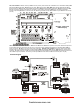
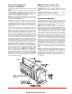
Placement of Equipment
in Chassis and Cabinet
The following guidelines outline the NFS-640’s flexible system
design.
Rows: The first row of equipment in the cabinet mounts in
chassis CHS-M2. Mount the second, third, or fourth rows of
equipment in chassis CHS-4MB (see NFS-640 Installation Man-
ual regarding panel output modules) or CHS-4L (for voice com-
ponents, see Voice Alarm System Manual).
Wiring: When designing the cabinet layout, consider separa-
tion of power-limited and non-power-limited wiring as discussed
in the NFS-640 Installation Manual.
Positions: A chassis offers four basic side-by-side positions for
components; the number of modules that can be mounted in
each position depends on the chassis model and the size of the
individual module. There are a variety of standoffs and hardware
items available for different combinations and configurations of
components.
It is critical that all mounting holes of the NFS-640 are secured
with a screw or standoff to ensure continuity of Earth Ground.
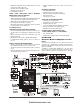
Layers: The CHS-M2 accepts four layers of equipment, includ-
ing the control panel. The CPU-640 fills three positions (left to
right) in the first-installed layer (the back of the chassis); its inte-
gral power supply occupies (the left) two positions in the next
two layers; the optional display occupies (the left) two positions
at the front, flush with the door. Panel output modules can be
mounted in several layers with standoffs or an L-bracket as
required. Some equipment, such as the NCA, may be door-
mounted directly in front of the control panel. The NCA mounts
onto the DP-DISP or ADP-4B. The NCA can be used as a pri-
mary display for the NFS-640 by directly connecting their net-
work ports (required in Canadian stand-alone applications).
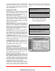
Expansion: Installing an LEM-320 Loop Expander Module
adds a second SLC loop to the control panel. The LEM-320 is
mounted onto the CPU-640, occupying the middle-right, second
(back) slot on the chassis. If networking two or more control
panels, each unit requires a NCM-W (wire) or NCM-F (fiber)
Network Control Module. The NCM-W/-F can be installed in any
panel output module position (see manual); the default position
is at the back of the chassis next to the control panel. Option
boards can be mounted in front of the LEM-320 or NCM mod-
ules; for ease of access, complete installation of those devices
before mounting another layer.
KDM-2 Controls and Indicators
Program Keypad: QWERTY type (keyboard layout).
8 LED indicators: Power; Fire Alarm; Pre-Alarm; Security;
Supervisory; System Trouble; Signals Silenced; Points Dis-
abled.
Membrane Switch Controls: Acknowledge/Scroll Display;
Signal Silence; Drill; System Reset; Lamp Test.
LCD Display: 80 characters (2 x 40) with long-life LED back-
light.
Configuration Guidelines
Stand-alone and network systems require a main display. On
single-CPU systems (one CPU-640/-640E), display options are
the KDM-2 or the NCA. On network systems (two or more CPU-
640/-640Es), at least one NCA or NCS annunciation device is
required. Other options listed as follows:
KDM-2: 80-character backlit LCD display with QWERTY pro-
gramming and control keypad. Order two BMP-1 blank modules
and DP-DISP mounting plate separately.
Requires top row of a
cabinet. Required for each stand-alone 80-character display
system. The KDM-2 may mount in network nodes to display
“local” node information as long as at least one NCA or NCS
network display is on the system to display network information.
NCA: Network Control Annunciator, 640 characters. On single
CPU-640/-640E systems, the NCA is the Primary Display for the
panel and connects directly to the CPU-640/-640E. On network
systems (two or more CPU-640/-640Es), one network display
(either NCA or NCS) is required for every system. On network
systems, the NCA connects (and requires) an NCM network
communications module. Mounts in a row of FACP node or in
two annunciator positions. Mounting options include the DP-
DISP, ADP-4B, or in an annunciator box, such as the ABS-2D. In
CAB-4 top-row applications, a DP-DISP and two BMP-1 blank
modules are required for mounting.
See NCA data sheet DN-
6858.
CPU-640: Central processing unit with integral 3.0 amp (6.0 A
in alarm) power supply for an NFS-640 system. Includes CPU;
one Signaling Line Circuit expandable to two; installation, pro-
gramming and operating manuals.
Order one per system or as
necessary (up to 103 network nodes) on a network system.
CPU-640E: Same as CPU-640 but requires 220 VAC, 1.5 amp,
(3.0 A in alarm).
CPU-640
KDM-2 shown with dress
plate, or NCA at front, flush
with door.
firealarmresources.com