
Instruction Manual

Document 51895 NCB-EL and NCB-FL Router Installation Rev. A 2/12/2002
5
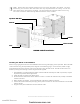
Installing the NCB-EL in the NISCAB-5
Mount a single gang electrical box in the NISCAB-5 back box using self tapping screws provided. Mount the HSP-
121B to the box using studs provided per the diagram on the following page. Once mounted, install a single,
grounded electrical outlet in the box and connect the output from the HSP-121B. The HSP-121B must be con-
nected to primary power through conduit using knockouts supplied.
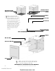
1. The NISCAB-5 is provided with three shelves and stand-offs for assembly of a shelf unit; however, only the
top shelf is required for these applications.
2. Install the shelf according to the above figure.
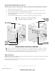
3. Run the Echelon network lines to the cabinet in conduit. Connect the network wires (or fiber) to the SMX
network transceiver.
4. When installing an NCB-EL, connect the Ethernet cable to the 10BaseT connector.
5. Connect the router transformer power plug to the power connector on the unit and slide the unit and shelf
into the cabinet.
6. Plug the router power transformer into the electrical outlet.
NOTE: Power-limited and nonpower-limited circuits must remain separated in the cabinet. All power-
limited wiring must remain at least 0.25 inches from any nonpower-limited circuit wiring. Run all non-
power-limited wiring along bottom of cabinet. All power-limited and nonpower-limited circuit wiring
must enter and exit the cabinet through different knockouts and/or conduits.
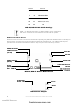
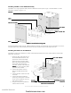
NISCAB-5 Shelf Installation
NISCAB-5NISCAB-5
NISCAB-5NISCAB-5
NISCAB-5
TT
TT
T
op Shelf for NCB Rop Shelf for NCB R
op Shelf for NCB Rop Shelf for NCB R
op Shelf for NCB R
outerouter
outerouter
outer
Shelves for PNETShelves for PNET
Shelves for PNETShelves for PNET
Shelves for PNET
-1-1
-1-1
-1
Stand-offsStand-offs
Stand-offsStand-offs
Stand-offs
CoverCover
CoverCover
Cover
www.PDF-Zoo.com
firealarmresources.com