
User Manual

dn-2225:a1 • 2/9/10 — Page 3 of 4
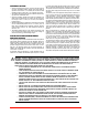
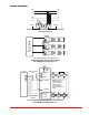
WIRING DIAGRAMS
+
++
+
–
–
–
–
––
++
F
A
C
P
ET ET
ET ET
ET ET
D
S
M
#
1
DSM #2
DSM #3
+
–
+
–
+
–
Strobe NAC Circuit
Strobe NAC Circuit
Strobe NAC Circuit
DSM Interconnectin
g
wirin
g
shown. Maximum of 20.
FACP
DSM
SYNC +
SYNC –
+
OUT 1
+ IN 1
MINUS 1
+ AUDIBLE
+ IN 2
MINUS 2
– AUDIBLE
Strobe NAC Circuit
OUT
ET ETET ETET ET ET
ET ETET
Strobe NAC Circuit
RETURN
+ OUT 2
Series ET Speaker and Strobe Operate Independently
(Non-Sync or Sync)
Series ET Speaker Strobes Synchronized
with DSM Module Single Class “A”
Series ET Speaker Strobe Appliances Synchronized
with DSM Module Single Class “A”
NOTE: Figure shows
interconnection to
strobe through sync
module. Speaker
portion requires 2
separate conductors to
FACP.
Strobe Speaker
2225bd1.wmf
2225bd2.wmf
2225bd3.wmf