20 HP Mini-Track Gas Loader Owner’s Manual WARNING: Read carefully and understand all OPERATING INSTRUCTIONS before operating. Failure to follow the safety rules and other basic safety precautions may result in serious personal injury.
Thank you very much for choosing a NorTrac™ product! For future reference, please complete the owner’s record below: Serial Number/Lot Date Code: ________________________________ Purchase Date: ____________________________________________ Save the receipt, warranty, and this manual. It is important that you read the entire manual to become familiar with this product before you begin using it. This 20 HP Mini Track Gas Loader is designed for certain applications only.
Table of Contents Intended Use .......................................................................................................................................... 4 Technical Specifications ...................................................................................................................... 4 Important Safety Information ............................................................................................................... 4 Safety and Product Labels .........................
Intended Use The NorTrac 20 HP Mini-Track Gas Loader is used for digging, carrying materials, grading, landscaping, ground maintenance, site preparation, and snow removal. With optional attachments (sold separately), the 20MTL is capable of sweeping, trenching, and more. The steer loader is designed for operation in small and limited-access spaces. Its standard mini-SSL interface and hydraulic connections make it compatible with many attachments to perform a wide variety of light and medium duty tasks.
⚠WARNING WORK AREA SAFETY • Inspect the work area before each use. Keep work area clean, dry, free of clutter, and well-lit. Cluttered, wet, or dark work areas can result in injury. Using the product in confined work areas may put you dangerously close to cutting tools and rotating parts. • Do not use the product where there is a risk of causing a fire or an explosion; e.g., in the presence of flammable liquids, gases, or dust.
the power switch is dangerous and must be repaired by an authorized service representative before using. • Disconnect the power/air supply from the product and place the switch in the locked or off position before making any adjustments, changing accessories, or storing the tool. Such preventive safety measures reduce the risk of starting the tool accidentally. • Store the product when it is not in use. Store it in a dry, secure place out of the reach of children.
⚠WARNING OPERATION • Only operate in good light, keeping away from holes and hidden hazards. • Be sure all drives are in neutral before starting the engine. Only start the engine from the operator's position. • Do not operate any of the control levers (including auxiliary lever) unless you are standing with both feet on the platform and firmly holding the grip handles. • Slow down and use extra care on hillsides. Be sure to travel in the recommended direction on hillsides.
any objects and do not contact them. • Ensure that you operate the loader unit in areas where there are no obstacles in close proximity to the operator. Failure to maintain adequate distance from trees, walls, and other barriers may result in injury. Only operate the unit in areas where there is sufficient clearance for the operator to safely maneuver the product. • Before digging, have the area marked for underground utilities, and do not dig in marked areas.
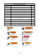
Safety and Product Labels Reference Number Description Quantity 1 Burn Hazard Warning Decal 1 2 Crush Hazard (Hand) Warning Decal 2 3 Crush Hazard (Body) Warning Decal 2 4 High-Pressure Fluid Hazard Warning Decal 3 5 Crush Hazard (Hand, Track) Warning Decal 2 6 Fire Hazard Danger Decal 1 7 Rotating Parts Warning Decal 1 8 Crush Hazard (Body, Access Panel) Warning Decal 1 9 Operational Warnings Decal (Impact, Rollover, Electrocution, Fall, General) 1 10 Start-up/Shut-down Instr
9. 10. 11. 12. 13. 14. Before Each Use ⚠WARNING • Evaluate the terrain to determine what accessories and attachments are needed to properly and safely perform the job. Only use accessories and attachments approved by the manufacturer. • Before digging, have the area marked for underground utilities, and do not dig in marked areas. Also, be aware of the location of objects and structures that may not be marked, such as underground storage tanks, wells, and septic systems.
• Clear debris in your work area. • Know and mark the location of any utility lines. Checking for Debris Note: The engine will overheat if it is operated with a blocked grass screen, a dirty or plugged cooling fin, and/or a cooling shroud removed. 1. Park the machine on a flat surface, lower the loader arms, and turn off the engine (turn ignition key to off). Remove the key. 2. Check the air filter pre-cleaner for debris. If required, wipe away debris before and during each use. 3.
Filling the Fuel Tank 1. Position the unit on a level surface, lower the loader arms, and turn off the engine by turning the ignition key to OFF. Remove the key. 2. Clean around the fuel tank cap and remove the cap. Use a funnel to add fuel (as specified above) to the fuel tank, filling until the fuel reaches 2-3 inches (60-70mm) below the top of the tank. This space is needed to allow the fuel to expand. Do not fill the fuel tank completely full. 3. Replace the fuel cap securely. Clean up any spilled fuel.
1. Check the hydraulic fluid level before the engine is started and after every 25 hours of operation. The fluid type is H68 or equivalent. The hydraulic tank capacity is 33 liters. 2. Position machine on level surface. Lower the loader arms and stop the engine. 3. Clean the area around filler neck of the hydraulic tank. 4. Remove the cap from the filler neck and check the fluid level. The fluid level should be approximately 75-100mm below the top of the tank. 5. If the level is low, add fluid. 6.
• Never operate without the guards securely in place. Be sure all interlocks are attached, adjusted, and functioning properly. • Do not change the engine governor setting or overspeed the engine. • Stop on level ground, lower implements, disengage the auxiliary hydraulics and shut off the engine before leaving the operator's position for any reason. • Keep hands and feet away from moving attachments. • Look behind and down before backing up to be sure of a clear path.
Important: Ensure the auxiliary hydraulic levers #3 and #4 are in the center position before attempting to start the engine. The most common cause for an engine not starting, not turning over fast enough, or the battery not having enough power, is that the auxiliary lever has been left on or knocked into gear and the engine is trying to start under load. Operating the 20MTL Starting and Stopping the Engine Starting 1. Stand on the platform. 2. Move the auxiliary hydraulics lever to the neutral position.
Operator Controls ⚠WARNING • Be sure all drives are in neutral before starting the engine. Only start the engine from the operator's position. • Do not operate any of the control levers (including auxiliary lever) unless you are standing with both feet on the platform and firmly holding the grip handles. • Do not carry a load with the arms raised. Always carry loads close to the ground. Loader Control Lever (Lift Arm and Bucket) (Lever 1) Forward......................Lower the loader arm Back........
Travel Speed Select Lever (Lever 5) Push forward to select high speed and push backward to select low speed. Operating hydraulic functions while traveling in high-speed mode will reduce machine travel speed. Drive Control Levers (Levers 6 and 7) • To move forward in a straight line, push the drive control levers (6 and 7) forward equally. To move backward in a straight line, pull the same drive control levers backward equally.
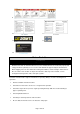
Instrumentation Panel Hydraulic Oil Pressure Indicator When the indicator is in the green range, it is normal. When the indicator is in the red range, stop the loader and replace the oil return filter. Fuel Gauge When the pointer is in the red range, the fuel is low. Stop the engine and refuel. Charging Indicator When the indicator is on the right of “0”, it is charging. When the indicator is on the left of “0”, check the battery.
Connecting the Bucket or Optional Attachments IMPORTANT: Use only manufacturer approved attachments. Attachments could change the stability and operating characteristics of the machine. The warranty of the machine may by void if used with unapproved attachments. IMPORTANT: Before connecting any attachments to the machine, make sure mount plates are free of dirt and debris. 1. Move the speed control lever to the SLOW (turtle) position. 2.
7. Move the auxiliary hydraulics lever forward, backward, and back to the neutral position to relieve hydraulic pressure at the hydraulic couplers. 8. Remove protective covers from the hydraulic couplers on the machine. Connect covers together to prevent contamination during operation. 9. Insert hydraulic connectors from attachment into the machine’s couplers. Note – female connector is connected onto male adaptor and male connector is inserted into female coupler. 10.
Moving a Non-functioning Machine ⚠WARNING • Never tow the machine! Hydraulic damage may occur. 1. Turn the ignition key to OFF to stop the engine. 2. Lift the entire machine off the ground using proper lifting equipment attached at the identified lifting points and move the machine. Maintenance ⚠WARNING • Disengage the auxiliary hydraulics, lower the attachment, stop the engine, and remove the key. Wait for all movement to stop and the unit to cool before adjusting, cleaning, or repairing.
• Park the machine on level ground. Never allow untrained personnel to service the machine. • Use jack stands to support components when required. • Carefully release pressure from components with stored energy. • Keep hands and feet away from moving parts. If possible, do not make adjustments with the engine running. • Keep all parts in good working condition and all hardware tightened. Replace all worn or damaged decals.
Maintain the machine by adopting a program of routine repair and maintenance in accordance with the following recommended procedures. It is recommended that the general condition of any tool be examined before it is used. Also refer to the engine manufacturer’s instruction manual for additional information about engine maintenance. The following chart is based on a normal operation schedule. Maintenance Interval Maintenance Point Check the hydraulic oil level and check for any external leaks.
If the filter or filter housing is damaged, stop the engine immediately and replace the damaged components. Failure to stop the machine when the air filter or housing is damaged could result in permanent engine damage. Loader Arm and Adaptor Plate Bushings 1. The equipment has 10 Duralon bushings and chromed pins. These are located on either end of your hydraulic cylinders and on all pivot points of the lift arms. 2. These bushings are wear part and require regular inspection.
3. Lower the loader arms, chock the track, and turn the ignition key to OFF to stop then engine. Remove the key. 4. Place the end of the hose in a pan. Remove the drain plug by turning counter-clockwise and allow engine oil to drain until empty 5. Check engine Owner’s Manual for filter change interval. Remove dirty filter and re-install clean filter as specified. 6. When the oil has drained completely, replace the plug and tighten to engine manufacturer’s specified torque.
Replacing the Fuel Filter ⚠WARNING • Never re-install a dirty filter. 1. Lower the loader arms and turn the ignition key to OFF to stop the engine. Remove the key. 2. Clamp the fuel line between the fuel tank and the fuel filter or move fuel shut-off valve to the “Closed” position, if equipped, to block the fuel flow. 3. Squeeze the ends of the hose clamps together and slide them away from the filter. 4.
• Never drain gasoline near an open flame or where a spark may ignite gasoline fumes. • Never smoke while handling fuel. 1. Park the machine on a level surface to assure fuel tank drains completely. 2. Lower the loader arms and turn the ignition key to the OFF position to stop the engine. Remove the ignition key from the key switch. 3. Loosen the hose clamp at inlet side of the fuel filter and slide it up the fuel line away from the fuel filter. 4.
Replace the Hydraulic Filter Check Hydraulic Lines After every 100 operating hours, check the hydraulic lines and hoses for leaks, loose fittings, kinked lines, loose mounting supports, wear, weather, and chemical deterioration. Replace all moving hydraulic hoses every 1500 hours or two years, whichever comes first. Make necessary repairs before operating. Every 500 Operating Hours 1. Position the machine on a level surface, lower the loader arms, and turn the ignition key to OFF to stop the engine.
10. Refill the hydraulic tank with approximately 33 liters of H68 hydraulic oil. 11. Clean up any spilled fluid. 12. Start the engine and let it run for about two minutes to purge any air from the system. Stop the engine and check for leaks. 13. Check the fluid level in the hydraulic tank and add oil to raise the level to the mark on the dipstick. DO NOT OVER FILL. Note: The correct level is 3 in. (75mm) below the top of the tank. Note: Properly dispose of all used oil, filters and oil-soaked rags.
4. Change the crankcase oil. Refer to engine’s manual. 5. For long-term storage (more than 90 days) add a stabilizer/conditioner additive to the fuel tank. a) Run the engine to distribute conditioned fuel through the fuel system (5 minutes). b) Stop the engine, allow it to cool, and drain the fuel tank. Refer to the fuel tank section. c) Restart the engine and run it until it stops. Repeat this process on CHOKE until the engine will not restart. d) Dispose of fuel properly. Recycle according to local codes.
Failure Engine will not start, starts hard, or fails to keep running. Engine loses power. Engine overheats. Possible Cause Corrective Action 2. Electrical connections are corroded or loose. 2. Clean and tighten electrical connections for good contact. 3. The relay switch is defective. 3. Contact the NorTrac Technical Service department (1-800-521-0438). 1. The auxiliary hydraulics lever is not in the neutral position. 1. Move the lever to the neutral position. 2. Fuel tank is empty. 2.
Failure Possible Cause Corrective Action 3. Traction pump drive coupler is loose or broken. 3. Inspect and tighten or replace as needed. Contact the NorTrac Technical Service department for parts assistance. 4. Pump and /or wheel motor is defective or damaged. 4. Inspect and repair or replace as needed. Contact the NorTrac Technical Service department for parts assistance. 5. Control valve is defective or damaged. 5. Inspect and repair or replace as needed.
Parts List Reference 1 2 3 4 5 6 7 8 9 10 Part Description Bucket Loading arm Tilt cylinder Control lever Frame Tool box Lift cylinder Muffler Sprocket Track Quantity 1 2 1 7 1 1 2 1 2 2 Replacement Parts • For replacement parts and technical questions, please call NorTrac Customer Service and Technical Support at 1-800-521-0438. • Not all product components are available for replacement.
Limited Warranty The 20 HP Mini-Track Gas Loader is sold by NorTrac; a division of Northern Tool & Equipment Company, Inc. (NTE). NorTrac will repair or replace, at its option, any part(s) thereof of the NorTrac 20 HP Mini-Track Gas Loader that are shown to be defective in material and/or workmanship, under normal use during the applicable 24-month warranty period. NorTrac wants your equipment to operate well and will assist you on repairs.
Distributed by: Northern Tool & Equipment Company, Inc. Burnsville, Minnesota 55306 www.northerntool.