
Product Manual

6
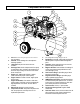
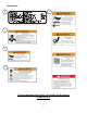
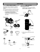
Component Identification
1. Pneumatic Tires: Keep tire pressure at 30 PSI for
easy movement.
2. Unloader: Vents discharge air to atmosphere in
start/stop operation.
3. Lifting Eyes: May also be used as tie down
locations.
4. Discharge Tube: Carries compressed air from pump
to safety/check valve, and then to the storage tank. It
becomes very hot during use and can cause severe
burns. Never touch.
5. Engine: NOT shipped with oil. Refer to engine
Owner’s Manual for proper oil and capacity.
6. Engine Controls: Location of choke, engine speed
and fuel valve.
7. Engine On/Off Switch: Turn switch to “ON” when
starting engine. CAUTION: Unit is not equipped with
high temperature “auto shutoff”. Do NOT allow to
overheat.
8. Manual Tube. Storage for owner’s manual.
9. Compressor Air Filter: Keep clean and particle free.
See “Pump Explosion and Pump Parts List” for
replacement part number.
10. Air Compressor Pump: Shipped with oil.
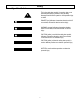
11. Belt Guard: Covers belt, engine pulley and flywheel.
NEVER operate compressor without belt guard in
place.
12. Regulator: Adjusts outlet pressure, not to exceed
pressure rating of attachment tool.
13. Magnetic Oil Drain: Removal allows for drainage of
oil from pump. Attracts metal particles that could
cause damage to pump.
14. Tank Pressure Gauge: Liquid filled gauge. Shows
pressure in receiver tank.
15. Regulated Pressure Gauge: Liquid filled gauge.
Shows regulated supply pressure.
16. ASME Safety/Check Valve: Automatically releases
air if tank exceeds preset pressure max. of 150 PSI.
A check valve is a pressure release port. Pull valve
pin to relieve pressure from receiver tank.
17. Quick Connect: This is a ¼” quick connect.
18. Air Receiver / Storage Tank: 20 gallon ASME
certified tank.
19. Tank Drain Valve: Used to remove moisture from air
after compressor is shut off and air emptied from
tank. Drain moisture daily after each use.