M157495U ITEM NUMBER: 157495 SERIAL NUMBER: _____________ Owner’s Manual Industrial Water Heater Instructions for Set-up, Operation, Maintenance & Storage Thank you for purchasing a NorthStar water heater. Your machine is designed for long life, dependability, and the top performance you demand! Take time now to read through this manual so you better understand the machine’s operation, maintenance and safety precautions. Everyone who operates this machine must read and understand this manual.
Table of Contents Equipment Protection Quick Facts ........................................................................................................................................ 1 TABLE OF CONTENTS ................................................................................................................................................ 2 ABOUT YOUR PRESSURE WASHER .........................................................................................................................
1. Recommended Service Parts List .................................................................................................................................... 20 2. Maintenance Mode ............................................................................................................................................................. 20 3. Maintenance Schedule .........................................................................................................................................
About Your Pressure Washer Thank you for purchasing a NorthStar Industrial Water Heater! It is designed for long life, dependability, and top performance. Site Selection. This unit is made for OUTDOOR USE ONLY unless specific exhausting guidelines are met. Read additional details in the “Before Each Use” section of this manual. Intended Use.
Specifications Item Number Max. Pressure Rating Max. Flow Output BTU Output Temperature Rise 157495 4000 PSI 4 GPM 353,700 BTU 190F @ 2GPM 190F @ 3GPM 140F @ 4GPM 250F #1 or 2 Diesel, Kerosene, Fuel Oil 4 gal. Maximum Temperature Approved Fuels Fuel Capacity Power Requirements NEMA Receptacle Volts Amps Hertz Phase Dimensions Length Width Height Weight (dry) Weight (fueled) Ship Weight 5-15R 115V 5A 60Hz single 38.25” 27” 38.75” 286 lbs. 334 lbs. 310 lbs.
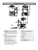
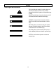
Component Identification 1. 2. 3. 4. 5. 6. 7. Water Outlet: Attach your high pressure hose. Control box: Box to house control switches. Heat Switch: When turned to ON position water heater will begin heating with proper water flow. Thermostat: Controls power to fuel solenoid for firing. Fuel Fill Cap: Vented cover for fuel tank. Fuel Tank: The Burner has a 4 gal. fuel tankkerosene, #1 or #2 diesel, or fuel oil may be used. Do not mix fuel types.
Special Equipment Safety Features 1. High Pressure Safety Device 2. Thermostat The high pressure safety device (rupture disc) is a backup safety feature. If the system’s pressure exceeds its limits, the rupture disc will open and relieve system pressure. The thermostat is another safety feature that keeps the outlet water temperature below 250F. Thermostat Rupture Disc WARNING: If the rupture disc ever discharges water, turn the unit off and do not use the machine.
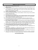
Important Safety Information 1.) 2.) 3.) 4.) 5.) 6.) 7.) 8.) 9.) 10.) 11.) 12.) 13.) 14.) 15.) 16.) 17.) 18.) Read all the instructions before using the product. Make sure that your existing hose, gun, and all accessories are rated for high temperatures and the appropriate pressure. To reduce the risk of injury, close supervision is necessary when the product is used near children. Do not allow irresponsible use by children.
Grounding Instructions This product must be grounded. If it should malfunction or breakdown, grounding provides a path of least resistance for electric current to reduce the risk of electrical shock. This product is equipped with a cord having an equipmentgrounding conductor and a grounding plug. The plug must be plugged into an appropriate outlet that is properly installed and grounded in accordance with all local codes and ordinances.
Safety Hazard Signal Word Definitions This is the safety alert symbol. It is used to alert you to potential personal injury hazards. Obey all safety messages that follow this symbol to avoid possible injury or death. DANGER (red) indicates a hazardous situation, which if not avoided, will result in death or serious injury. DANGER WARNING (orange) indicates a hazardous situation, which if not avoided, could result in death or serious injury.
Safety Decal Locations WARNING Skin puncture and burn hazard. Hot high pressure fluid can puncture and burn skin resulting in serious injury including amputation. -Use only components that are rated to 250°F and 4000 psi. -Do not attach pressure washers that exceed 4000 psi. -Do not direct spray at people. Part No. 787751 WARNING 1.) Risk of electrocution. Electrical shock can kill you. -Do not expose the water heater or any electrical product to the water heater's spray.
Un-Packing Instructions Inspect water heater immediately after delivery for missing parts or damage. For missing or damaged components, contact Product Support at 1-800-270-0810. Handle & Grip Qty-2 Wheel Qty-2 Hardware Bag Qty-1 Water Heater Qty-1 Remove 2 retaining blocks.
Hardware Bag Owner’s Manual 4X - 5/16 X .75” Flange Bolt 4X - 5/16 Flange Nut 2X - 5/8 X 3.
Assembly To attach handles, use: 5/16 X .75” Flange Bolts (4x) 5/16 Flange Nuts (4x) To attach wheels: 1.) Slide 5/8 X 3.5” bolt through hub of wheel. 2.) Spin 5/8 Jam Nut onto bolt. Do not tighten against wheel. 3.) Slide bolt through hole in frame, secure with 5/8 Hex Nut. 5/8 Hex Nut 5/8 Jam Nut 5/8 X 3.5” Hex Bolt 1. Attach handles, see above. 2. Attach wheels, see above. 3. Remove water heater from the pallet.
Before Each Use After Machine Has Cooled: 1. Remove burner fuel cap. 2. Add fuel through the fill opening. Do not overfill. Allow at least 1/2” of empty space below fill neck to allow for fuel expansion. 3. Replace fuel cap securely before starting burner. 4. Clean up fuel spills/splashes immediately. If possible, move the machine away from spilled fuel on the ground. Wipe up spilled fuel and wait 5 minutes for excess fuel to evaporate before starting burner.
For Indoor and Outdoor Uses 1.) Turn the pump and heat switches on (Refer to “Operation” for details). Have someone operate the spray gun so the burner fires. 2.) Loosen the locking screw and close the air band until black smoke appears from the burner exhaust vent. Note the position of the white arrow on the air band. 3.) Slowly open the air band until white smoke just starts to appear. 4.) Turn the air band half way back to the black smoke position previously noted. Tighten the locking screw. 5.
1. For a product rated at 125 volts or less, the GFCI is built into the power cord plug. This GFCI device provides additional protection from the risk of electric shock. If replacement of the plug or cord is needed, use only identical replacement parts. 2. For a product rated at more than 125 volts, a receptacle based GFCI is required. DANGER: Electrocution hazard Improper connection of the equipment or grounding conductor can result in a risk of electrocution.
Operation Instructions 1. Pre-Operation A.) Position the machine for easy access to all controls. B.) Position the machine on a solid surface, with less than a three degree slope, and so it is protected from external damage. C.) Position the machine so that ambient lighting is sufficient for the surface you are cleaning to be seen with ease. Use artificial light if needed. D.) Check hoses, fittings, and fuel connections for signs of wear, cracks and looseness, and replace as required. E.
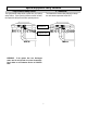
4. To Start Adjustment Knob DANGER: Do not point the spray wand at yourself or at any person. Bodily injury may result from hot water or water under high pressure. WARNING: Wear eye, ear, hand, foot, and skin protection at all times while operating this water heater. 1. Turn water supply ON. 2. Squeeze the trigger to allow air to purge from the system. This step goes faster with the pressure nozzle removed. High Pressure Hose Water Outlet Diluted Chemical Chemical Injector Strainer 00322 2.
Maintenance & Repair WARNING: Unauthorized machine modification or use of non-approved replacement parts may cause personal injury and/or property damage and will void the manufacturer warranty. All mechanical equipment, no matter how well designed, will need repairs. A NorthStar water heater is no exception. At times, a NorthStar water heater may be inoperable because repairs are required.
7. Coil Descaling 8. Coil Desooting In hard water areas, scale build-up within the heating coil will occur. Scale deposits will decrease the water temperature rise and may eventually clog the heating coil. 1. Mix scale remover in a 5 gallon bucket and elevate the bucket so it is higher than the pump on your pressure washer. 2. Attach water heater’s inlet hose to the high pressure outlet of your pressure washer. 3.
9. Electrodes 4.Clean off carbon deposits that may have accumulated on the tips of the electrodes. 5. Reset the spacing as shown below. On a yearly basis the electrodes should be inspected and any necessary adjustments made. 1. Block up the front of the water heater 6 inches. 4 Nuts 2. Remove the 4 nuts that attach the burner to the heating chamber. You do not have to disconnect the fuel lines or the electric cords, but be careful not to subject them to excessive strain.
1) Disconnect the swivel fitting from elbow to the inlet of the coil Shuttle Assembly (Side View) Swivel Fitting Magnet Shuttle Assembly (Bottom View) 2) Remove the “Cap” fitting from the flow switch. 4) Observe the “Shuttle Assembly” and internal portion of “Body” for obstructions, hard water deposits and any other foreign debris. Remove the foreign debris with light scraping or compressed air. If no additional cleaning is required continue to Step 7.
5) Remove the “Body” from the plastic “Enclosure” and soak the “Body” in CLR or similar solution to dislodge excess buildup. The screws (QTY 5) in the “Enclosure” are TORX T10. 9) Inspect the O-ring on the “Cap”, if it is damaged, replace the entire flow switch assembly. To order a replacement flow switch assembly, call Northstar Product Support at 1800-270-0810. If the O-ring is not damaged, reinstall the “Cap” onto the “Body”. Torque the cap to 100lb-in.
Moving and Handling Instructions 1. Maneuvering Your Water Heater 2. Lifting Your Water Heater 1. Lift handles with both hands until the wheels come in contact with the ground and the frame is lifted off of the ground. 1.To reduce risk of injury, it is recommended to use a hoist to lift this water heater. 2. Lift from four lifting points. 2. Push the water heater forward if it is being moved on solid, smooth ground. (concrete, hard-packed dirt) 3.
Troubleshooting Guide Water Heater Will Not Run - No Power Solutions Plug machine in. Make sure machine is dry. Press RESET on the GFCI. Turn heat switch ON. Check for tripped circuit breaker in building. Causes Machine not plugged in GFCI tripped Machine turned OFF Line circuit breaker tripped GFCI Trips During Operation Solutions Check the voltage. Make sure connections are dry and off of the ground. Check extension cord section on page 3 for more guidelines.
Parts Explosion- 157495- Rev U 27
Parts List–157495- Rev U ITEM 1 2 3 4 5 6 7 8 9 10 11 13 14 15 16 17 18 19 20 22 23 24 25 26 27 28 29 30 31 32 33 34 35 36 37 38 39 40 41 42 43 44 45 46 47 48 49 50 52 54 55 56 58 59 60 PART# 5027 38379 797121 787394 794626 780127 30822 777914 22502 305267 801075 30501 787751 35894 38482 305180 790561 37525 30747 801077 30754 37524 KEL202725 777727 777119 777340 17141 801490 31976 306401 777111 82125 82126 789074 82123 305239 799864 801490 36400 38120 790040 779232 33387 777915 777337 305208 790017 38398 3
Wiring Diagrams 29
Limited Warranty Dear Valued Customer: The NorthStar Product you just purchased is built with the finest material and craftsmanship. Use this product properly and enjoy the benefits from its high performance. By purchasing a NorthStar product, you show a desire for quality and durability. Like all mechanical equipment this unit requires a due amount of care. Treat this unit like the high quality piece of machinery it is. Neglect and improper handling may impair its performance.
California Proposition 65 Information WARNING: This product can expose you to chemicals including gasoline engine exhaust, which is known to the State of California to cause cancer, and carbon monoxide, which is known to the State of California to cause birth defects or other reproductive harm. For more information go to www.P65Warnings.ca.gov. Manufactured by Northern Tool + Equipment Co., Ltd Burnsville, MN 55306 NorthernTool.