
Network Router User Manual


Web OS 10.0 Application Guide
Chapter 2: VLANs
59
212777-A, February 2002
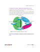
In the example shown in Figure 2-6, if default gateways 5 or 6 fail, then traffic is directed to
default gateway 1, which is configured with IP address 10.10.4.1. If default gateways 1
through 4 are not configured on the switch, then packets from VLAN 2 and VLAN 3 are dis-
carded.
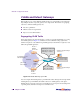
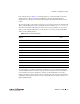
The route cache table on the switch records each session request by mapping the destination IP
address with the MAC address of the default gateway. The command /info/arp/dump on
the switch command line will display the entries in the route cache similar to those shown in
Table 2-3. The destination IP addresses (see the last two rows) are associated with the MAC
addresses of the default gateways.
As shown in Table 2-3, traffic from VLAN 2 uses Gateway 5 to access destination IP address
192.168.20.200. If traffic from VLAN 3 requests the same destination address, then traffic is
routed via Gateway 5 instead of Gateway 6, because 192.168.20.200 in the route cache is
mapped to Gateway 5. If the requested route is not in the route cache, then the switch reads the
routing table. If the requested route is not in the routing table, then the switch looks at the con-
figured default Gateway.
Table 2-3 Route Cache Example
Destination IP
address
Flags MAC address VLAN Port Referenced
ports
10.10.1.1 P 00:60:cf:46:48:60 4 1-9
10.10.1.20 00:60:cf:44:cd:a0 4 1 empty
10.10.1.30 00:60:cf:42:3b:40 4 2 empty
10.10.4.1 00:60:cf:42:77:e0 1 3 empty
10.10.4.40 P 00:60:cf:46:48:60 1 1-9
172.21.2.27 00:50:da:17:c8:05 2 7 1
172.21.2.200 P 00:60:cf:46:48:60 2 1-9
172.21.3.14 00:c0:4f:09:3e:56 3 8 2
172.21.2.200 P 00:60:cf:46:48:60 3 1-9
192.168.20.200 R 00:60:cf:44:cd:a0 4 1 7
200.1.2.200 R 00:60:cf:42:3b:40 4 2 8