
Network Router User Manual


Web OS 10.0 Application Guide
Chapter 13: Firewall Load Balancing
331
212777-A, February 2002
Configure Connectivity for the Primary Dirty-Side Web Switch
1. Configure VLANs on the primary dirty-side Web switch.
Two VLANs are required. VLAN 1 includes port 1, for the Internet connection. VLAN 2
includes port 2, for the firewall connection, and port 9, for the interswitch connection.
NOTE – Port 1 is part of VLAN 1 by default and does not require manual configuration.
2. Configure IP interfaces on the primary dirty-side Web switch.
Three IP interfaces (IF’s) are used. IF 1 is on placed on Subnet 1. IF 2 will be used for routing
traffic through the top firewall. IF 3 will be used for routing traffic through the lower firewall.
To avoid confusion, IF 2 and IF 3 will be used in the same way on all Web switches.
NOTE – By configuring the IP interface mask prior to the IP address, the broadcast address is
automatically calculated. Also, only the first IP interface in a given subnet is given the full sub-
net range mask. Subsequent IP interfaces (such as IF 3) are given individual masks.
3. Turn Spanning Tree Protocol (STP) off for the primary dirty-side Web switch.
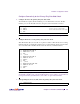
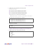
>> # /cfg/vlan 2
>> # add 2 (Port 2 connects to the firewall)
>> # add 9 (Port 9 is the inter-switch connection)
>> # ena
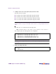
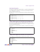
>> # /cfg/ip/if 1
>> # mask 255.255.255.0
>> # addr 195.1.1.10
>> # ena
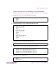
>> # ../if 2
>> # mask 255.255.255.0
>> # addr 10.10.2.1
>> # vlan 2
>> # ena
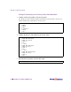
>> # ../if 3
>> # mask 255.255.255.255
>> # addr 10.10.2.2
>> # vlan 2
>> # ena
>> # /cfg/stp/off