
Network Router User Manual


Web OS 10.0 Application Guide
Chapter 13: Firewall Load Balancing
319
212777-A, February 2002
Configuring Basic FWLB
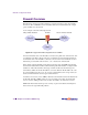
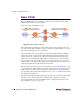
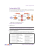
The steps for configuring basic FWLB are provided below. While two or four switches can be
used, the following procedure assumes a simple network topology with only two Web switches
(one on each side of the firewalls) as shown in Figure 13-4.
Figure 13-4 Basic FWLB Example Network
Configure the Dirty-Side Web Switch
1. Configure VLANs.
NOTE – Alternately, if using hubs between the switches and firewalls and you do not wish to
configure VLANs, you must enable Spanning Tree Protocol to prevent broadcast loops.
2. Define the dirty-side IP interface.
In addition to one IP interface for general switch management, there must be one dirty-side IP
interface for each firewall path being load balanced. Each must be on a different subnet.
>> # /cfg/ip/if 1 (Select IP interface 1)
>> IP Interface 1# addr 192.16.12.1 (Set address for switch management)
>> IP Interface 1# mask 255.255.255.0 (Set subnet mask for interface 1)
>> IP Interface 1# ena (Enable IP interface 1)
>> IP Interface 1# ../if 2 (Select IP interface 2)
>> IP Interface 2# addr 10.1.1.1 (Set the IP address for interface 2)
>> IP Interface 2# mask 255.255.255.0 (Set subnet mask for interface 2)
>> IP Interface 2# ena (Enable IP interface 2)
>> IP Interface 2# ../if 3 (Select IP interface 3)
>> IP Interface 3# addr 10.1.2.1 (Set the IP address for interface 3)
>> IP Interface 3# mask 255.255.255.0 (Set subnet mask for interface 3)
>> IP Interface 3# ena (Enable IP interface 3)
"Dirty" Side "Clean" Side
Internet
Firewall 1
Firewall 2
Servers
Web Switch 1
IF1: 192.16.12.1
Web Switch 2
IF1: 20.1.1.1
Virtual Server:
20.1.1.10
20.1.1.2
20.1.1.3
Dirty Side:
10.1.2.10
IF2: 10.1.1.1
IF3: 10.1.2.1
IF2: 10.1.3.1
IF3: 10.1.4.1
Dirty Side:
10.1.1.10
Clean Side:
10.1.4.10
Clean Side:
10.1.3.10
1
2
3
2
3
4
5