
Network Router User Manual


Web OS 10.0 Application Guide
Chapter 1: Basic IP Routing
31
212777-A, February 2002
Example of Subnet Routing
Prior to configuring, you must be connected to the switch Command Line Interface (CLI) as
the administrator.
NOTE – For details about accessing and using any of the menu commands described in this
example, see the Web OS Command Reference.
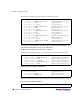
1. Assign an IP address (or document the existing one) for each real server, router, and cli-
ent workstation.
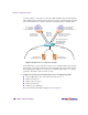
In the example topology in Figure 1-2 on page 30, the following IP addresses are used:
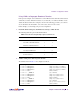
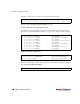
2. Assign an IP interface for each subnet attached to the switch.
Since there are five IP subnets connected to the switch, five IP interfaces are needed:
Table 1-1 Subnet Routing Example: IP Address Assignments
Subnet Devices IP Addresses
1 Primary and Secondary Default Routers 205.21.17.1 and 205.21.17.2
2 First Floor Client Workstations 100.20.10.1-254
3 Second Floor Client Workstations 131.15.15.1-254
4 Third Floor Client Workstations 208.31.177.1-254
5 Common Servers 206.30.15.1-254
Table 1-2 Subnet Routing Example: IP Interface Assignments
Interface Devices IP Interface Address
IF 1 Primary and Secondary Default Routers 205.21.17.3
IF 2 First Floor Client Workstations 100.20.10.16
IF 3 Second Floor Client Workstations 131.15.15.1
IF 4 Third Floor Client Workstations 208.31.177.2
IF 5 Common Servers 206.30.15.200