
Network Router User Manual


Web OS 10.0 Application Guide
Chapter 12: Global Server Load Balancing
301
212777-A, February 2002
3. On the Denver switch, define a real server group.
4. On the Denver switch, define a virtual server.
5. On the Denver switch, define the type of Layer 4 processing each port must support.
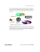
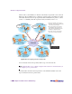
In this example, the following ports are being used on the Alteon 180 Web switch:
The ports are configured as follows:
6. On the Denver switch, enable SLB.
>> Real server 2# ../group 1 (Select real server group 1)
>> Real server group 1# add 1 (Add real server 1 to group 1)
>> Real server group 1# add 2 (Add real server 2 to group 1)
>> Real server group 1# health http (Use HTTP for health checks)
>> Real server group 1# content index.html (Set URL content for health checks)
>> Real server group 1# ../virt 1 (Select virtual server 1)
>> Virtual server 1# vip 179.14.70.1 (Assign IP address)
>> Virtual server 1# service http (Select the HTTP service menu)
>> Virtual server 1 http service# group 1 (Associate virtual port to real group)
>> Virtual server 1 http service# ../ena (Enable the virtual server)
Table 12-4 Web Host Example: Alteon 180 Port Usage
Port Host Layer 4 Processing
3 Server C Server
4 Server D Server
5 Default Gateway Router. This connects the switch to the Internet
where all client requests originate.
Client
>> Virtual server 1# /cfg/slb/port 3 (Select physical switch port 3)
>> SLB port 3# server ena (Enable server processing on port 3)
>> SLB port 3# ../port 4 (Select physical switch port 4)
>> SLB port 4# server ena (Enable server processing on port 4)
>> SLB port 4# ../port 5 (Select physical switch port 5)
>> SLB port 5# client ena (Enable client processing on port 5)
>> SLB port 5# /cfg/slb (Select the SLB Menu)
>> Layer 4# on (Turn SLB on)