
Network Router User Manual


Web OS 10.0 Application Guide
186
Chapter 7: Filtering
212777-A, February 2002
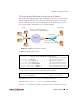
Configuring a Filter-Based Security Solution
Before you begin, you must be connected to the switch CLI as the administrator.
In this example, all filters are applied only to the switch port that connects to the Internet. If
intranet restrictions are required, filters can be placed on switch ports connecting to local
devices.
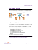
Also, filtering is not limited to the few protocols and TCP or UDP applications shown in this
example. See Table 7-1 on page 171 and Table 7-2 on page 171 for a list of other well-known
protocols and applications.
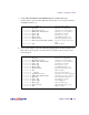
1. Assign an IP address to each of the network devices.
For this example, the network devices have the following IP addresses on the same IP subnet:
2. Create a default filter that will deny and log unwanted traffic.
The default filter is defined as Filter 224 in order to give it the lowest order of precedence:
NOTE – Because the proto parameter is not tcp or udp, the source port (sport) and desti-
nation port (dport) values are ignored and may be excluded from the filter configuration.
Table 7-4 Web Cache Example: Real Server IP Addresses
Network Device IP address
Local Subnet 205.177.15.0 - 205.177.15.255
Web Server 205.177.15.2
Mail Server 205.177.15.3
Domain Name Server 205.177.15.4
>> # /cfg/slb/filt 224 (Select the default filter)
>> Filter 224# sip any (From any source IP addresses)
>> Filter 224# dip any (To any destination IP addresses)
>> Filter 224# proto any (For any protocols)
>> Filter 224# action deny (Deny matching traffic)
>> Filter 224# name deny unwanted traffic (Provide a descriptive name for the
filter)
>> Filter 224# ena (Enable the default filter)
>> Filter 224# adv/log enable (Log matching traffic to syslog)